This clock do have really big digits ![]()
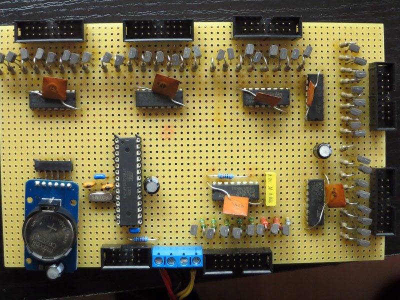
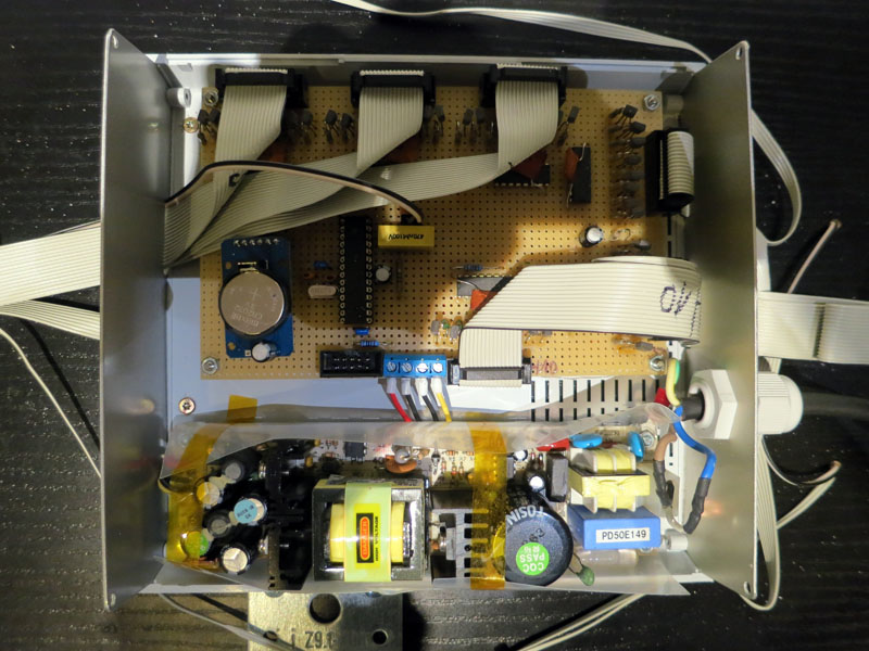
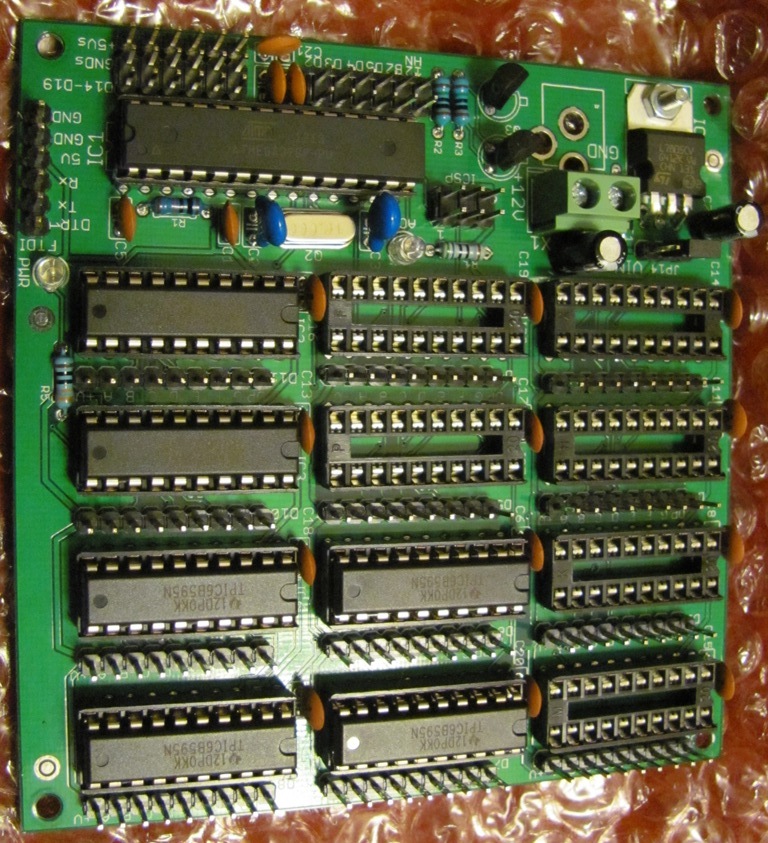
schematic isn't big deal. 6x 74HC595 shift registers, a lot of small transistors and resistors. Timebase is a RTC module with DS3231. This module I adjust 2 times per year on breadboard.
The digits are self adhesive LED-stripes with 120 LED per meter. You can cut this stripe each 2,5 cm. My segments are 12,5 cm long (hours and minutes) seconds 7,5cm. A big digit is 26 cm. My board is a rack board from DIY-market with 30 x 120 cm
You can scale up this digits so big, as you want and it's much easier as handle with some dozen 5mm LEDs ![]()
The stripe is really bright. Next step was a phototransistor to dimm the display per PWM with the output enable pins from shift registers.
/* based on LucidTronix 4 Digit sketch
 * modifyed by Ger@ld 1/2014
 * Daisy Chained Shift Registers
 * 6x 74HC595 connected to 7-Segment LED display
 * with DS3231 Real time clock chip
 * Tutorial at:
 * http://www.lucidtronix.com/tutorials/52
 * September 2013
 */
#include <Wire.h>
#include "RTClib.h"

RTC_DS1307 RTC;

int dataPin = 10;
int latchPin = 8;
int clockPin = 9;
int fotPin = 3;    // select the input pin for phototransistor; GND to E phototransistor C to input + 1M --> +5V
int dimPin = 6;    // select the pin to drive Output Enable from shift registers (pin 13)
int fotVal = 0;    // variable to store the value coming from the sensor

byte dec_digits[] = {0b10111111,0b00000110,0b11011011,0b01001111,0b11100110,0b01101101,0b11111101,0b00000111,0b11111111,0b01101111 };

void setup() {
  //set pins to output so you can control the shift register
  pinMode(latchPin, OUTPUT);
  pinMode(clockPin, OUTPUT);
  pinMode(dataPin, OUTPUT);
  pinMode(dimPin, OUTPUT);  // declare the Dim_Pin as an OUTPUT

  Wire.begin();
  RTC.begin();
  if (! RTC.isrunning()) {
    RTC.adjust(DateTime(__DATE__, __TIME__));
  }
}

void loop() {
  DateTime now = RTC.now();
  int thehour = now.hour();
  // switch between 24 hour clock and 12 hour clock
 // if (thehour > 12 ) thehour -= 12;
  int hour_tens = thehour / 10;
  int hour_ones = thehour % 10;
  int minute_tens = now.minute() / 10;
  int minute_ones = now.minute() % 10;
  int second_tens = now.second() / 10;
  int second_ones = now.second() % 10;

  digitalWrite(latchPin, LOW);
  shiftOut(dataPin, clockPin, MSBFIRST, dec_digits[second_ones]);
  shiftOut(dataPin, clockPin, MSBFIRST, dec_digits[second_tens]);
  shiftOut(dataPin, clockPin, MSBFIRST, dec_digits[minute_ones]);
  shiftOut(dataPin, clockPin, MSBFIRST, dec_digits[minute_tens]);
  shiftOut(dataPin, clockPin, MSBFIRST, dec_digits[hour_ones]);
  shiftOut(dataPin, clockPin, MSBFIRST, dec_digits[hour_tens]);
  //take the latch pin high so the LEDs will light up:
  digitalWrite(latchPin, HIGH);
  {
  fotVal = analogRead(fotPin);            // read the value from the sensor
  fotVal = map(fotVal, 0, 1023, 0, 254);  // scale it to use it with the LED - map to 254, cause 255 is complete off

  analogWrite(dimPin, fotVal);            // set brightness
 }
  // pause before next value:
  delay(100);
}
A better description from my project is on german board:
http://forum.arduino.cc/index.php?topic=207948.0
Gerald