I'm making a controller that will read the temperature and humidity using four sensors (DTH11) and then use a relay to turn on/off a heater and humidifier. My code is below. The problem I'm having is that my code is not switching the digital pins from HIGH to LOW. I checked the states of the pins using a multimeter with both reading 0V. I am getting positive readings from the sensors on the serial output so I would think that the pins should switch from LOW to HIGH? Any help is much appreciated and thank you in advance for the help!
#include "DHT.h"
#include <Boards.h>
#include <Firmata.h>

#include <SoftwareSerial.h>

#define DHTPIN1 A1
#define DHTPIN2 A2
#define DHTPIN3 A5
#define DHTPIN4 A5

#define DHTTYPE DHT11

DHT dht1(DHTPIN1, DHTTYPE);
DHT dht2(DHTPIN2, DHTTYPE);
DHT dht3(DHTPIN3, DHTTYPE);
DHT dht4(DHTPIN4, DHTTYPE);

void setup() {
 Serial.begin(9600);
 Serial.println("DHTxx test!");

 pinMode(A1, INPUT);
 pinMode(A2, INPUT);
 pinMode(A4, INPUT);
 pinMode(A5, INPUT);
 pinMode(2, OUTPUT);
 pinMode(3, OUTPUT);

 dht1.begin();
 dht2.begin();
 dht3.begin();
 dht4.begin();

}

void loop() {
 // Wait a few seconds between measurements.
 delay(2000);

 // Reading temperature or humidity takes about 250 milliseconds!
 // Sensor readings may also be up to 2 seconds 'old' (its a very slow sensor)
 float h1 = dht1.readHumidity();
 // Read temperature as Celsius (the default)
 float t1 = dht1.readTemperature();
 // Read temperature as Fahrenheit (isFahrenheit = true)
 float f1 = dht1.readTemperature(true);

 float h2 = dht2.readHumidity();
 float t2 = dht2.readTemperature();
 float f2 = dht2.readTemperature(true);

 float h3 = dht3.readHumidity();
 float t3 = dht3.readTemperature();
 float f3 = dht3.readTemperature(true);

 float h4 = dht4.readHumidity();
 float t4 = dht4.readTemperature();
 float f4 = dht4.readTemperature(true);

 // Check if any reads failed and exit early (to try again).
 if (isnan(h1) || isnan(t1) || isnan(f1)) {
   Serial.println("Failed to read from DHT sensor 1!");
   return;
 }

 if (isnan(h2) || isnan(t2) || isnan(f2)) {
   Serial.println("Failed to read from DHT sensor 2!");
   return;
 }

 if (isnan(h3) || isnan(t3) || isnan(f3)) {
   Serial.println("Failed to read from DHT sensor 3!");
   return;
 }

 if (isnan(h4) || isnan(t4) || isnan(f4)) {
   Serial.println("Failed to read from DHT sensor 4!");
   return;
 }

 float ht=(h1+h2+h3+h4)/4.0;
 float tt=(t1+t2+t3+t4)/4.0;
 float ft=(f1+f2+f3+f4)/4.0;

 Serial.print("Humidity: ");
 Serial.print(ht);
 Serial.print(" %\t");
 Serial.print("Temperature: ");
 Serial.print(tt);
 Serial.print(" *C ");
 Serial.print(ft);
 Serial.print(" *F\t");

 if(ht>0){
   digitalWrite(2,HIGH);
 }

 if(ft>0){
   digitalWrite(3,HIGH);
 }
}
Moderator edit: </mark> <mark>[code]</mark> <mark>
Hmmmm that's strange. I can't run the sketch since I don't have the libraries, but I stripped all that stuff out and hardcoded values of ht and ft in all combos of >0 and <0 and put some leds on pins 2 and 3..... they were on and off as expected.
Any chance those libraries might have high-jacked the pins for any reason?
You sure those pins work ok in a simple test sketch?
weedpharma:
Use serial messages to see what is happening.
Good point.... just move some of the Serial.print() lines from just above the "ifs" (which I assume are the ones telling you the values are correctly >0) into the "ifs".
OldSteve:
I see nothing in the code in 'loop()' that would ever turn the LEDs off, only on.
That's what I was looking for too: thought perhaps they were on-ing at the bottom of loop() and off-ing again at the top making it seem they never went on.
JimboZA:
That's what I was looking for too: thought perhaps they were on-ing at the bottom of loop() and off-ing again at the top making it seem they never went on.
He just needs a couple of 'else's. (He said they turn on but don't turn off.) Edit: Actually, he appears to say both:-
The problem I'm having is that my code is not switching the digital pins from HIGH to LOW.......I am getting positive readings from the sensors on the serial output so I would think that the pins should switch from LOW to HIGH?
Still, they're never made LOW in 'loop()'.
And I just edited and added 'HIGH' and 'LOW' to my last reply, in case the LEDs were connected to +V instead of ground.
I didn't read it correctly then, the not switching from high to low. You're right on that OldSteve, needing the else to do that.
But this part.....
paintballer008:
I checked the states of the pins using a multimeter with both reading 0V. I am getting positive readings from the sensors on the serial output so I would think that the pins should switch from LOW to HIGH?
.... made me think he wasn't getting high voltages in the first place. Sounds like his sensor values are positive as he expects, but the pins aren't high?
sorry everyone for taking so long to reply. So I thought the problem was the the pins were not switching from LOW to HIGH but i checked this by adding leds to the circuit connected to the pins and they light up meaning the pins are reading HIGH. But I still have the problem of the relay not switching. The relay stays normally open even though the voltage is set to high, which should cause the switch to close. I'm assuming it has something to do with DHT library but am unaware of a solution. If anyone has any threads where this has already been discussed could you please send me the link. I have also triple checked the wiring to the relay as well as tried a new relay in case the other one was bad but still nothing. Thanks again everyone.
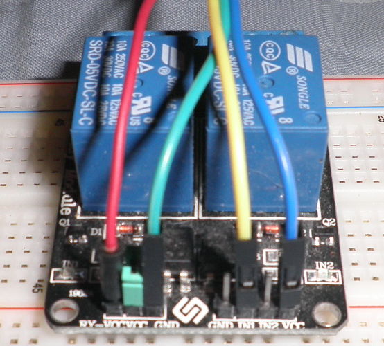
I'm using a SainSmart 2-channel 5V Relay Module. The problem was the power supply i was using was not giving enough power to trigger the relay. But using USB its now able to trigger the relay, BUT it seems as though theres not enough power still? What is happening now is my relay switches to high, the lights I have connected to the relay come one for a second or two then switch off. After maybe five seconds the relay switches back on and the process repeats. I notice once the relay switches on, the LEDs I have connected start dim and then go out, but once the relay switches to off, the LEDs switch back on to full strength and this process repeats likewise.
Correct, so I need an external power source for the relay (i.e. not coming from the arduino)? Any idea the easiest way to accomplish this since you're right here? I'm sure I can figure it out myself with some time if you're busy so no worries either way and thanks for the help!
I am still unsure what to use as an external power supply. It's not the wiring I'm confused with, but what power supply is acceptable. Would using something similar to this be acceptable by cutting off the end and using the positive wire for VCC and other for ground?
What's an acceptable power supply to power my relay?