code for dc -dc converter

Im working on a dc-dc buck boost converter, with 2 different switching elements for bidirectional operation:

#include <PID_v1.h>
#include <math.h>

float pwPin1 = 5;
float pwPin2 = 6;
float analogPin1 = 1;
float analogPin2 = 2;
float analogPin3 = 3;
float value1 = 0;
float value2 = 0;
float boostDuty = 0;
float buckDuty = 0;
int v1 = 0;

double Input1;
double Output1;
double Setpoint1;
double Input2;
double Output2;
double Setpoint2;

double aggKp1 = 1, aggKi1 = 0.5, aggKd1 = 1;              // settiing aggressive values of Kp Ki Kd for PID1
double consKp1 = 0.1, consKi1 = 0.05, consKd1 = 0.25;    // settiing aggressive values of Kp Ki Kd for PID1

double aggKp2 = 1, aggKi2 = 0.5, aggKd2 = 1;              // settiing aggressive values of Kp Ki Kd for PID2
double consKp2 = 0.1, consKi2 = 0.05, consKd2 = 0.25;    // settiing aggressive values of Kp Ki Kd for PID2

PID myPID1(&Input1, &Output1, &Setpoint1, consKp1, consKi1, consKd1, DIRECT);        //PID1
PID myPID2(&Input2, &Output2, &Setpoint2, consKp2, consKi2, consKd2, DIRECT);        //PID2

void setup()
{
  pinMode(pwPin1, OUTPUT);                                //set PWM 5 to output
  pinMode(pwPin2, OUTPUT);                                //set PWM 6 to output
  Input1 = analogRead(analogPin1);                               //take feedback of output in boost mode to PID1
  Input2 = analogRead(analogPin2);                               //take feedback of output in boost mode to PID2
  Setpoint1 = 777;                                        // set point for PID1
  Setpoint2 = 491;                                        // set point for PID2
  myPID1.SetMode(AUTOMATIC);                                // turn ON PID1
  myPID2.SetMode(AUTOMATIC);                                //turn on PID2
  TCCR0B = TCCR0B & B11111000 | B00000001;                  // set freq. of PWM to 62.5kHz
}

void loop()
{
  TCCR0B = TCCR0B & B11111000 | B00000001;
  Input1 = analogRead(analogPin1);
  Input2 = analogRead(analogPin2);
  v1 = analogRead(analogPin3);

  double gap1 = abs(Setpoint1 - Input1);                 //distance away from setpoint
  double gap2 = abs(Setpoint2 - Input2);                 //distance away from setpoint

  if (gap1 < 10)
  {
    myPID1.SetTunings(consKp1, consKi1, consKd1);
  }
  else
  {
    myPID1.SetTunings(aggKp1, aggKi1, aggKd1);
  }

  if (gap2 < 10)
  {
    myPID2.SetTunings(consKp2, consKi2, consKd2);
  }
  else
  {
    myPID2.SetTunings(aggKp2, aggKi2, aggKd2);
  }

  if (v1 <= 511 && v1 > 306)
  {
    do            // boost converter  fn.
    {
      Input1 = analogRead(analogPin1); //read A2
      boostDuty = 1 - (Input1 / 778);  //calculate boost  duty ratio
      myPID1.Compute();
      analogWrite(pwPin2, (boostDuty * 255 * Output1)); //write to D6

    }
    while (v1 > 306);

  }

  else
  {
    do   //buck converter fn.
    {
      Input2 = analogRead(analogPin2);
      value1 = Input2 / 4.01;
      buckDuty = value1 / 202;
      myPID2.Compute();
      analogWrite(pwPin1, buckDuty * Output2);
    }
    while (v1 < 511);
    
    v1 = analogRead(analogPin3);
    if (v1 = 0)
      analogWrite(pwPin1, 0);
  }
}

As per value of v1 the buck mode or boost mode gets selected.Im facing the following problems:

  1. The buck mode does not seem to generate a PWM??

  2. Ive used 2 seperate PID fns. ...can someone please check wether ive applied correctly? especially the output statement?

  3. I based the duty ration of buck & boost fn on the basic voltage eqn. for buck and boost converter...is that fine...and ive multipled it with output1 & output 2 of PID??

  4. The processor is heating up??why?

  5. Is the if ..else statement used for selecting boost and buck function correct???

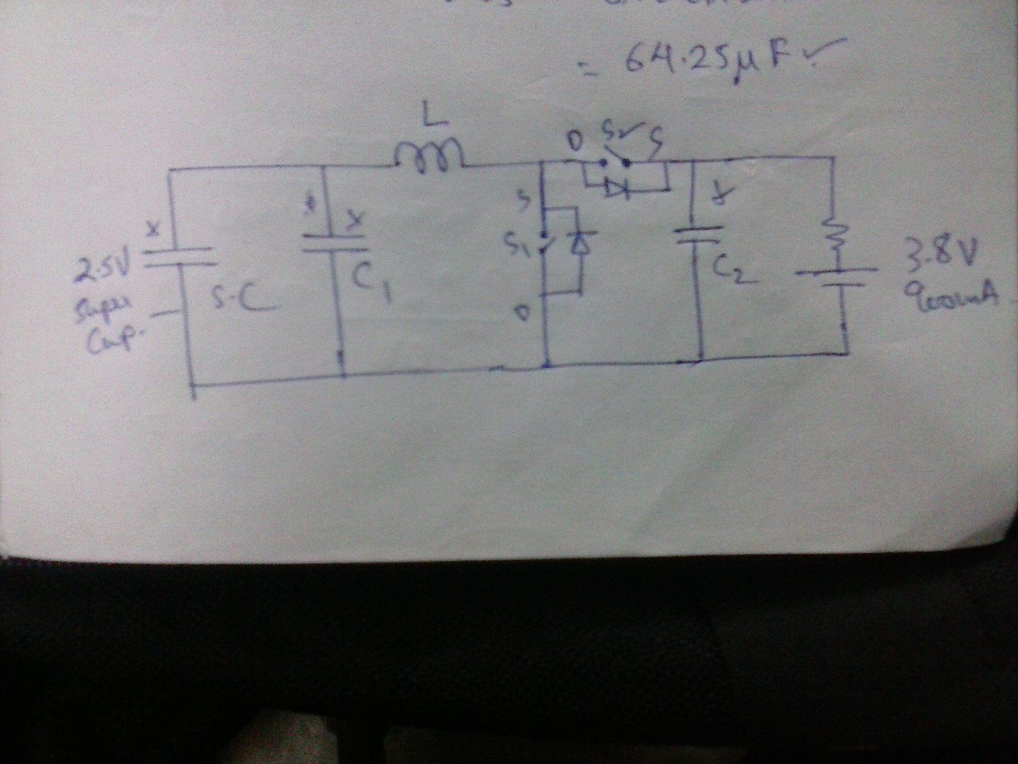
Ive attached the power circuit diagram for your reference..

Please help have a project submission.....

Thanks & regards
Emmanuel

float pwPin1 = 5;
float pwPin2 = 6;
float analogPin1 = 1;
float analogPin2 = 2;
float analogPin3 = 3;

Pin numbers are NOT floating point values.

I quit reading at that point.

The S and D markings on your "switches" seem at odds with the diodes marked.

You have no high-side driver?

hi MarkT/PaulS

Thanks for the reply...

I havent shown the driver but ive considered the same...its a TLP250 opto -driver....ill correct the S..D foul up...

The value to pins are integers??

could you please help me out with the following points:
"

  1. The buck mode does not seem to generate a PWM??

  2. Ive used 2 seperate PID fns. ...can someone please check wether ive applied correctly? especially the output statement?

  3. I based the duty ration of buck & boost fn on the basic voltage eqn. for buck and boost converter...is that fine...and ive multipled it with output1 & output 2 of PID??

  4. The processor is heating up??why?

  5. Is the if ..else statement used for selecting boost and buck function correct???
    "

Emmanuel

Please edit your post, select the code, and put it between [code] ... [/code] tags.

You can do that by hitting the "Code" button above the posting area (It looks like a scroll with < > inside it).

How to use this forum


  v1 = analogRead(analogPin3);
    if (v1 = 0)
      analogWrite(pwPin1, 0);

do            // boost converter  fn.
    {
      Input1 = analogRead(analogPin1); //read A2
      boostDuty = 1 - (Input1 / 778);  //calculate boost  duty ratio
      myPID1.Compute();
      analogWrite(pwPin2, (boostDuty * 255 * Output1)); //write to D6
    }
    while (v1 > 306);

Where does v1 change in that loop?

float pwPin1 = 5;

Input pins can float, but that doesn't mean . . .

float pwPin1 = 5;

You could also consider making it const. Is the number 5 going to change?

Please post a complete schematic, including the Arduino connections and optoisolators. You will need it to get a good grade on the project, anyway...

Then maybe we can tell you why it is heating up. Or it will dawn on you as soon as you look at it.

v1 is from analog pin 3, it is connected to a supercapacitor which discharges from 2.5V to 1.5V...

AWOL:

float pwPin1 = 5;

Input pins can float, but that doesn't mean . . .

i think i got the syntax wrong...what i meant was "PWM pin no. 5 is a float value and variable name im using for pin no.5 is pwPin1 ..."?????

v1 is from analog pin 3, it is connected to a supercapacitor which discharges from 2.5V to 1.5V...

Now answer my question:

Where does v1 change in that loop?

aarg:
Please post a complete schematic, including the Arduino connections and optoisolators. You will need it to get a good grade on the project, anyway...

Then maybe we can tell you why it is heating up. Or it will dawn on you as soon as you look at it.

ok...will do best i can to put it online...

Ok...v1 is not updated in that loop....right?i.e i havent called the analogRead there...?correct?

no. 5 does not change...its not a constant...but it referes to PWM pin 5....cud you pl tell me th correct declaration.???

 const byte pwPin1 = 5;

ok...thanks ...could you pl have a look at the PID part input and out put of PID..?

# include <math.h>
#include <PID_v1.h>

const byte pwPin1 = 5;
const byte pwPin2 = 6;
int analogPin2 = 3;
int analogPin1 = 0;
float v1 = 0;
float boostDuty = 0;
float buckDuty = 0;

double Input1;
double Output1;
double Setpoint1;

double aggKp1 = 2, aggKi1 = 1, aggKd1 = 2;              // settiing aggressive values of Kp Ki Kd for PID1
double consKp1 = 0.1, consKi1 = 0.05, consKd1 = 0.25;    // settiing conservative values of Kp Ki Kd for PID1

PID myPID1(&Input1, &Output1, &Setpoint1, consKp1, consKi1, consKd1, DIRECT);        //PID1

void setup()
{
  pinMode(pwPin1, OUTPUT);
  pinMode(pwPin2, OUTPUT);
  Setpoint1 = 778;                                        // set point for PID1
  myPID1.SetMode(AUTOMATIC);                                // turn ON PID1
  TCCR0B = TCCR0B & B11111000 | B00000001;
}

void loop()
{
  TCCR0B = TCCR0B & B11111000 | B00000001;
  Input1 = analogRead(analogPin1);
  v1 = analogRead(analogPin2);
  double gap1 = abs(Setpoint1 - Input1);                 //distance away from setpoint

  if (gap1 < 10)
  {
    myPID1.SetTunings(consKp1, consKi1, consKd1);
  }
  else
  {
    myPID1.SetTunings(aggKp1, aggKi1, aggKd1);
  }


  do
    {
      v1 = analogRead(analogPin2);
      Input1 = boostDuty;
      myPID1.Compute();
      boostDuty = 1 - (v1 / 778);  //calculate boost  duty ratio
      analogWrite(pwPin2, (Output1*boostDuty)); //write to D6
      if ( boostDuty > 0.603 || boostDuty < 0.3421) {
        analogWrite(pwPin2, (boostDuty = 0));
      }

    }
    while (v1 > 307);
  }

Ive implemented a PID from the example, the PID does not seem to be responding, can some one please check the if there is any syntax error in the implementation??

Emmanuel

what i meant was "PWM pin no. 5 is a float value

No. PWM pins are either on or off, just like any other digital pin. The difference is that they are off and on with quite short intervals between the changes. The duty cycle, another int value, defines the ratio of on to off and off to on intervals, but the intervals are ints. There is nothing about a PWM pin that involves a float - not the pin number, not the value written to a PWM pin, and not the value read from a PWM pin.

PaulS:
No. PWM pins are either on or off, just like any other digital pin. The difference is that they are off and on with quite short intervals between the changes. The duty cycle, another int value, defines the ratio of on to off and off to on intervals, but the intervals are ints. There is nothing about a PWM pin that involves a float - not the pin number, not the value written to a PWM pin, and not the value read from a PWM pin.

thanks paulS..

do you have an example code for implemention a PID function with autotune??

i have to implement that in the code...ive been searching for an example code which uses the required syntax on arduino.cc,...but couldnt get any??

Emmanuel

Hi!

does anyone have an example code for implemention a PID function with Autotune??

i have to implement that in the code for my project...ive been searching for an example code which uses the required syntax on arduino.cc,...but couldnt get any??