Header file:http://textuploader.com/ddh93
.cpp file:http://textuploader.com/ddh9i
Okay guys I am trying to get working code for 2 H-bridges (L293d) controlled with 74HC_HCT595 shift register
http://www.nxp.com/documents/data_sheet/74HC_HCT595.pdf
#include <AFMotor.h>


int main(void)
{
  AF_DCMotor motor_1(1);
  AF_DCMotor motor_2(2);
  AF_DCMotor motor_3(3);
  AF_DCMotor motor_4(4);

  motor_1.setSpeed(200);
  motor_2.setSpeed(200);
  motor_3.setSpeed(30);
  motor_4.setSpeed(30);
    while (1)
    {
    motor_1.run(FORWARD);
    motor_2.run(FORWARD);
    }
}
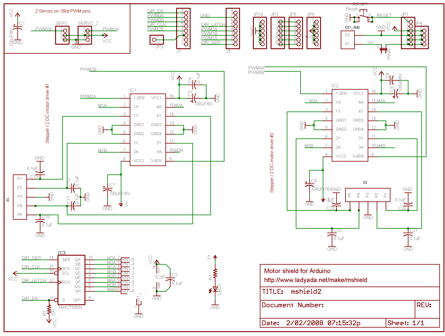
I've found the this schematics on the internet:
and made my connections using the proteus picture in the attachment.
I've tried to measure voltages on the motor outputs and it shows 0 volts.
It seems that there is a problem with
// STCP	Pin 12	Storage Register Clock Input
#define LATCH 4
#define LATCH_DDR DDRB
#define LATCH_PORT PORTB

// SHCP	Pin 11 Shift Register Clock Input
#define CLK_PORT PORTD
#define CLK_DDR DDRD
#define CLK 4

// OE	Pin 13	Output enable input (Aktivan na LOW)
#define ENABLE_PORT PORTD
#define ENABLE_DDR DDRD
#define ENABLE 7

// DS	Pin 14	Serial Data Input
#define DATA 0
#define DATA_DDR DDRB
#define DATA_PORT PORTB
Could someone provide a schematics for the Arduino connections to SHIFT REGISTER?
Robin2
December 19, 2016, 8:34am
3
I reckon you will get advice much more quickly if you make a simple drawing showing how you have everything connected and post a photo of your drawing.
...R
Robin2:
...R
Well I have used the already built Motor driver:
So basically I wasn't connecting anything together.
so it this shield is really practical.
When I work directly with registers DDRn PORTn for controlling shift register motors do not run. But it works well using already written functions such us pinMode and digitalWrite and that doesnt make any sense to me.
This is the source code:
// Adafruit Motor shield library
// copyright Adafruit Industries LLC, 2009
// this code is public domain, enjoy!


#if (ARDUINO >= 100)
  #include "Arduino.h"
#else
  #if defined(__AVR__)
    #include <avr/io.h>
  #endif
  #include "WProgram.h"
#endif

#include "AFMotor.h"


static uint8_t latch_state;
show original
// Adafruit Motor shield library
// copyright Adafruit Industries LLC, 2009
// this code is public domain, enjoy!

/*
 * Usage Notes:
 * For PIC32, all features work properly with the following two exceptions:
 *
 * 1) Because the PIC32 only has 5 PWM outputs, and the AFMotor shield needs 6
 *    to completely operate (four for motor outputs and two for RC servos), the
 *    M1 motor output will not have PWM ability when used with a PIC32 board.
 *    However, there is a very simple workaround. If you need to drive a stepper
 *    or DC motor with PWM on motor output M1, you can use the PWM output on pin
 *    9 or pin 10 (normally use for RC servo outputs on Arduino, not needed for
 *    RC servo outputs on PIC32) to drive the PWM input for M1 by simply putting
 *    a jumber from pin 9 to pin 11 or pin 10 to pin 11. Then uncomment one of the
 *    two #defines below to activate the PWM on either pin 9 or pin 10. You will
 *    then have a fully functional microstepping for 2 stepper motors, or four
 *    DC motor outputs with PWM.
 *
show original
They use following pins
In the header file lines 120-134
#define LATCH 4
#define LATCH_DDR DDRB
#define LATCH_PORT PORTB
#define CLK_PORT PORTD
#define CLK_DDR DDRD
#define CLK 4
#define ENABLE_PORT PORTD
#define ENABLE_DDR DDRD
#define ENABLE 7
#define SER 0
#define SER_DDR DDRB
#define SER_PORT PORTB
But those pins are wrong,t so I changed them according to the datasheet pinout.
Digital pin 12 --> PB6
From this code I figured out that they are using those pins for controlling shift register since it's hard to see lines on PCB.
#define MOTORLATCH 12
#define MOTORCLK 4
#define MOTORENABLE 7
#define MOTORDATA 8
and
pinMode(MOTORLATCH, OUTPUT);
pinMode(MOTORENABLE, OUTPUT);
pinMode(MOTORDATA, OUTPUT);
pinMode(MOTORCLK, OUTPUT);
Robin2
December 21, 2016, 8:36am
5
One knows this is a super-professional project when one reads "chip every road and bridge " on the website
Is there any reason to conclude that the datasheet you found is identical to the physical product you have?
My suggestion is to buy a product that comes with proper documentation and some example programs.
...R
Okay I've debugged it, for making ti simple I connected 8 LEDs to shift registers pins 16 - 9
So if anyone bought this item it could be of use:
https://drive.google.com/open?id=0BzNMcs6QcbfMRnhyWDd4TXo1QVU
This shield is really badly documented.
Robin2
December 22, 2016, 10:11am
7
SimpleThings:
Glad to hear you have figured it out.
Perhaps you could write a short tutorial for the benefit of others?
...R
Of course I could just tell me under what forum section should I upload it?
Robin2
December 22, 2016, 7:54pm
9
SimpleThings:
Just post it as a Reply in this Thread and keep a bookmark so you can refer others to it.
...R
Also this shield shows some really weird behaviour:
Connected 4 toy DC motors:
Arduino connected to the IR receiver via interrupt pin+ motorshield controlling 4 DC motors
Shield only supplied with power via USB
Max 2 motors start rotating slowly and after few seconds usb port gets disconnected from the PC
Shield only supplied with external DC power supply 8 VDC, 600 mADC
Not a single key press gets printed on the screen from arduino.
Shield supplied with both external DC power supply 8 VDC, 600 mADC + USB connected to the PC
Key pressed gets received.