I recently purchased the following Coin Acceptor online:
Here's the manual:
And I started hooking it up to my Arduino (pictured below)
As you can see, so far I have the Black wire connected to the GND terminal (on my screw shield),
and the White wire connected to the digital pin 2.
However, the two remaining wires Red and Grey are putting me off and I want to make sure that I don't end up frying the whole thing. I'd say this is my first intermediate project with the Arduino so I'm coming on here just to make sure I'm doing this correctly.
On the manual, it indicates that the working voltage is 12V, however from what I know, the Arduino's max is 5V. I did a bit of research and even asked on the seller's Amazon page and I got a "Yes it can run on the Arduino", also there is a whole Instructables tutorial on getting it to run with the Arduino but they seem to gloss over how to actually hook it up.
Could someone please explain to me if it is possible and how?
Also, the Grey wire is suppose to be hooked up to "Counter", I'm not exactly sure what to do with that one because the Coin Counter is on the Coin Acceptor itself to my knowledge and that is what I have all the wires plugged into. I have a guess that it may have something to do with the following though:
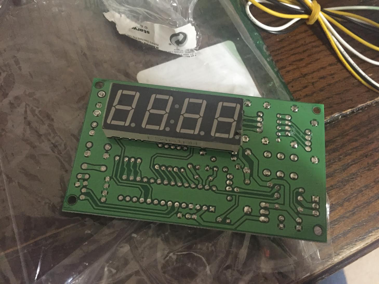
The seller also included a separate board with a Coin Counter (pictured below) along with 4 USB cables, but did not provide instruction on how to connect that to the Coin Acceptor, here's a link to pics of the board:
The board also came with 2 cables, with wires having open ends. The smaller one is pictured plugged into the board (and has 2 wires) and the larger one is directly above the board in the picture (and has 3 wires).
Find another tutorial besides instructables, its basically beginners trying to teach beginners. Do a google search of the model of the coin machine. Or even google using generic terms with arduino and coin acceptor. There is hundreds of tutorials for this project.
One thing I will tell you is most coin machines need to be programmed before they will send any kind of signal that an arduino can read.
codlink:
Find another tutorial besides instructables, its basically beginners trying to teach beginners. Do a google search of the model of the coin machine. Or even google using generic terms with arduino and coin acceptor. There is hundreds of tutorials for this project.
Hey codlink,
Unfortunately the reason I came asking here is because, while there may be many tutorials out there, I am referring to specific problems that I am having with this coin acceptor and the related wiring.
I have researched and nothing I have found clearly explains the wiring process, they all just skip to programming/setting up the settings for the coin acceptor.
Here is something I just recently found:
Again, there's not much description but from what I can tell, the Red wire is being relayed to a 12V power source and the Black wire is plugged into both the GND of the Arduino and relayed to the power source (in order to establish a shared Ground connection, as explained briefly on the website: http://redpaperheart.com/blog/2014/08/prototype-coin-acceptor/).
I don't know what the Grey cable is linked too as it isn't pictured, but again, it's most likely the exterior Counter board.
well, it seems fairly obvious that the red wire is positive and black is negative...
then, the the white and grey wires are both signal cables....
the white cable tells you how many coins of the same type have been inserted, and the grey cable tells you what kind of coin.
and it looks like it does it within .6 seconds..
so you need something that will tell you how many time your data pin went from low to high during that time frame, and then based on that, what kind of coin.
You will need to find out if the signals are at 12v (ala the coin box supply) or if the coin box reduces that to say 5V. Does the documentation say anything about signal voltages?
If those lines are at 12V you'll need to bring that down somehow, perhaps with a voltage divider. Don't stick those wires into an Arduino until you clarify that.
I've attached a more readable version of the instructions you included for this device.
Have you got as far as programming the coin selector unit with the coins you wish to accept ?
The instructable which you have linked does not appear to use the gray wire at all. The Arduino sketch illustrated, appears to derive the information that a coin has been inserted, and its value (pulse count) from the white (signal) wire.
const int coinInt = 0;
//Attach coinInt to Interrupt Pin 0 (Digital Pin 2). Pin 3 = Interrpt Pin 1.

volatile float coinsValue = 0.00;
//Set the coinsValue to a Volatile float
//Volatile as this variable changes any time the Interrupt is triggered
int coinsChange = 0;
//A Coin has been inserted flag

void setup()
{
  Serial.begin(9600);
//Start Serial Communication
  attachInterrupt(coinInt, coinInserted, RISING);
//If coinInt goes HIGH (a Pulse), call the coinInserted function
//An attachInterrupt will always trigger, even if your using delays
}

void coinInserted()
//The function that is called every time it recieves a pulse
{
  coinsValue = coinsValue + 0.05;
//As we set the Pulse to represent 5p or 5c we add this to the coinsValue
  coinsChange = 1;
//Flag that there has been a coin inserted
}

void loop()
{
  if(coinsChange == 1)
//Check if a coin has been Inserted
  {
    coinsChange = 0;
//unflag that a coin has been inserted

    Serial.print("Credit: £");
    Serial.println(coinsValue);
//Print the Value of coins inserted
  }
}
The additional board you have received (with 4 USB sockets) appears to be the "time control board" on the vendor's home page http://www.coin-selector.com/ . It is an extra and almost certainly not essential to the functioning of the coin selector.
JimboZA:
You will need to find out if the signals are at 12v (ala the coin box supply) or if the coin box reduces that to say 5V. Does the documentation say anything about signal voltages?
If those lines are at 12V you'll need to bring that down somehow, perhaps with a voltage divider. Don't stick those wires into an Arduino until you clarify that.
Thanks for the reply,
I don't see anything about signal voltages on the manual.
Would something like this work to bring the voltage down?
6v6gt:
I've attached a more readable version of the instructions you included for this device.
Have you got as far as programming the coin selector unit with the coins you wish to accept ?
Hey 6v6gt,
I'd like to at least power the coin selector and get it linked to the Arduino before I begin programming it, the code/configuration isn't really part of my concern since most tutorials and guides I've looked over seem to cover that aspect in depth. The real problem I am having is figuring out whether I can power the acceptor directly with my Arduino (since, according to to two replies on the seller's page, it appears to be possible) or whether (as suggested above) I need to bring the voltage down. Any suggestions?
I would have configured the coin selector first, so as to be able to measure the voltage on the white wire when a coin is inserted. It is quite possible that, although the supply voltage is 12 Volts, it has an internal regulator, and the signal voltage may be lower (say 5Volt).
Anyway, assuming that the signal output voltage is 12 Volts and you want to reduce it to 5 Volts, a potential divider solution has already been suggested.
For these voltages (low signal current) you could try a pair of resistors in series say 6.8K and 4.7K.
White Wire --> 6.8K --> 4.7K ---> Common Ground. The junction between the 2 resistors is connected to the Arduino pin.
6v6gt:
I would have configured the coin selector first, so as to be able to measure the voltage on the white wire when a coin is inserted. It is quite possible that, although the supply voltage is 12 Volts, it has an internal regulator, and the signal voltage may be lower (say 5Volt).
I appreciate the link to the support page, I will get in contact with them and see if the coin acceptor does in fact come with an internal regulator.
In terms of configuring the coin selector first as you stated, would you mind running me through that process? As in what I need to power the coin acceptor on it's own (I'm assuming that simply red/black wires -> 12V battery and as stated, I'd have to measure the voltage on the white wire once a coin is inserted, is that correct?)
VerFloe:
. . .
In terms of configuring the coin selector first as you stated, would you mind running me through that process? As in what I need to power the coin acceptor on it's own (I'm assuming that simply red/black wires -> 12V battery and as stated, I'd have to measure the voltage on the white wire once a coin is inserted, is that correct?)
Exactly. Power it with 12 volts ( red = + , black = ground). Insulate the bare ends of the white and grey cables. Follow the instructions under heading "The Setting Process for Parameters" and then you should have it configured to accepts some types of coin.
All you need to do is take a different power supply of 12V connect it to the coIn acceptor red to positive and black to negative and connect different power supply or 5v to arduino or u could connected it to your PC. Now short arduino ground and 12V power supply ground. Here the white pin or coin pin sends impulses on what you program the coin acceptor to give, example if you set it to give 5 pulses for p1 coin and 10 pulses for p2 coin, it sends those respective pulses when you insert those types of coins in the acceptor. And if u wanna verify these impulses jus connect a led to coin(white) pin directly instead of arduino and insert those coins so for p1 coin led blinks 5 times.
OP -
Look for forum member RUFFSTA
He has all the information - but doesn't know how to understand it.
We went through this entire process a couple of months ago.