Communication problem between nano V3.0 and PTZ camera

Hi everybody!

I allow myself to open this topic because I have a small problem which made me lose tufts of hair .. here is my problem:

I'm on a personal project, I bought this camera 4.

To motorize it using dynamixel AX12A servomotors (to avoid shaking in the backlash of inexpensive servos and thus have a clean rendering).

For communication, I bought an RS485 to TTL module:
Here it is 2

I was able to recover and slightly modify a code which works very well, and so I managed my first version using a UNO R3 card and a "smart servo shield" from DFrobot.

my block with the arduino card and its shield being much too big by my eyes, I would therefore like to use a Nano V3.0 card.

I changed library to be able to order my servos without shield.

So I did again my connections with the nano, added a small 12-> 5V transformer for its power supply and turned everything on. Everything is at its nominal voltage, but it does not work.
I do have the TXD led of the module and TX of the card which flash at the same rate as the orders that I send from my return camera (on another PC), so I receive something.

But when I print my frame on the serial monitor, I realize that I only get empty frames
(0000000)

what bothers me is that it works great with the UNO R3 with or without shield ...

and I did not find any similar topics other than those which helped me to make my V1.

maybe a pilot problem?

Do you have any advice for me?

Thanks in advance for your time.

 * module rs485 :
 *          -TXD (out module) sur RX carte
 *          _relier gnd cam au gnd IN module
 * 
 * 
 * 
 */
/*-----( Import needed libraries )-----*/
#include <SPI.h>
#include <ServoCds55.h>


/*-----( Declare Constants and Pin Numbers )-----*/
#define ID_Pan 1
#define ID_Tilt 2
#define RS485lTxControl 4   //RS485 Direction control 
#define RS485Transmit    HIGH   // not needed here, the servos attached to the arduino will not transmit any data to the Pelco-D controller  
#define RS485Receive     LOW
#define Pin13LED         13

/*-----( Declare objects )-----*/
ServoCds55 myservo;
/*-----( Declare Variables )-----*/
byte byteReceived[7];
int byteNumber = 0;
int byteSend;
int minPulse1     =  100;   // minimum servo position
int maxPulse1     =  212; // maximum servo position
int turnRate1     =  1;  // servo turn rate increment (larger value, faster rate)
int minPulse2     =  138;  // minimum servo position
int maxPulse2     =  178; // maximum servo position
int turnRate2     =  1;  // servo turn rate increment (larger value, faster rate)
/** The Arduino will calculate these values for you **/
int centerservoPAN;
int centerservoTILT;
int pulseWidth1;          // servo pulse width
int pulseWidth2;          // servo pulse width


void setup() {
  Serial.begin (9600);
  myservo.begin ();
  myservo.setVelocity(50);
  centerservoPAN = maxPulse1 - ((maxPulse1 - minPulse1)/2);
  centerservoTILT = maxPulse2 - ((maxPulse2 - minPulse2)/2);
  pulseWidth1 =  centerservoPAN;
  pulseWidth2 =  centerservoTILT;
  Serial.println("Arduino Serial Servo Control with Pelco D");
  Serial.println();
  
  pinMode(Pin13LED, OUTPUT);   
  pinMode(RS485lTxControl, OUTPUT);    
  digitalWrite(RS485lTxControl, RS485Receive);  // Init Transceiver   
  delay(10000);
  Serial.println("initialisation des moteurs");
  myservo.WritePos(ID_Pan,pulseWidth1);
  myservo.WritePos(ID_Tilt,pulseWidth2);
  Serial.println("ready");
}//--(end setup )---


void loop() {
//  if (!Serial.available())Serial.println("pas de co");
  if (Serial.available() > 0)  //Look for incoming serial data from Pelco-D controller
   {
    
    byteReceived[byteNumber ++] = Serial.read();    // Read received byte
    //Serial.println(byteReceived[byteNumber], DEC);        // Show on Serial Monitor
    delay(10);
    if ( byteReceived[0] != 0xFF ) {byteNumber = 0;}   // When Byte 0 isn't 0xFF (Pelco 1st Byte) reset byteNumber to 0 preventing the serial port being blocked.
   }
    if ( byteNumber > 6 )                                 // process it
    {                 
      byteNumber = 0;                                 // ready for next time
      byte data = byteReceived[3];       // read the incoming byte:
      Serial.println(data, HEX);        // Show on Serial Monitor
      switch(data)
        {
          case 0x00 :  break;
          case 0x02 :  pulseWidth1 = pulseWidth1 - turnRate1; myservo.WritePos(ID_Pan,pulseWidth1); break; // right
          case 0x04 :  pulseWidth1 = pulseWidth1 + turnRate1; myservo.WritePos(ID_Pan,pulseWidth1); break; // left   
          case 0x10 :  pulseWidth2 = pulseWidth2 - turnRate1; myservo.WritePos(ID_Tilt,pulseWidth2); break; // down
          case 0x08 :  pulseWidth2 = pulseWidth2 + turnRate1; myservo.WritePos(ID_Tilt,pulseWidth2); break; // up
          case 0x14 :  pulseWidth1 = pulseWidth1 + turnRate1; myservo.WritePos(ID_Pan,pulseWidth1); pulseWidth2 = pulseWidth2 - turnRate1; myservo.WritePos(ID_Tilt,pulseWidth2); break; // left-up
          case 0x12 :  pulseWidth1 = pulseWidth1 - turnRate1; myservo.WritePos(ID_Pan,pulseWidth1); pulseWidth2 = pulseWidth2 - turnRate1; myservo.WritePos(ID_Tilt,pulseWidth2); break; // right-up
          case 0x0C :  pulseWidth1 = pulseWidth1 + turnRate1; myservo.WritePos(ID_Pan,pulseWidth1); pulseWidth2 = pulseWidth2 + turnRate1; myservo.WritePos(ID_Tilt,pulseWidth2); break; // left-down
          case 0x0A :  pulseWidth1 = pulseWidth1 - turnRate1; myservo.WritePos(ID_Pan,pulseWidth1); pulseWidth2 = pulseWidth2 + turnRate1; myservo.WritePos(ID_Tilt,pulseWidth2); break; // right-down
        }
        
        // stop servo pulse at min and max
        if (pulseWidth1 > maxPulse1) { pulseWidth1 = maxPulse1; }
        if (pulseWidth1 < minPulse1) { pulseWidth1 = minPulse1; }
        // stop servo pulse at min and max
        if (pulseWidth2 > maxPulse2) { pulseWidth2 = maxPulse2; }
        if (pulseWidth2 < minPulse2) { pulseWidth2 = minPulse2; }
       
    // print pulseWidth back to the Serial Monitor (uncomment to debug)
    Serial.println("Servo 1: ");
    Serial.println(pulseWidth1);
    Serial.println(" Servo 2: ");
    Serial.println(pulseWidth2);
    Serial.println("degrees");
   }
}````
How are you powering the servos?

More links please !

Servo AX-12A : https://www.robotis.us/dynamixel-ax-12a/. That is a serial/UART servo motor.
The stall current is 1.5A.
When the servo motor is stalled or when it starts to move it might have a peak current of 1.5A. Do you have that available for the servo motor ?

DFrobot Smart Digital Servo Shield: https://www.dfrobot.com/product-958.html with schematic.

Do you use the DFrobot ServoCds55 library without the shield ?
Where is that library ? I can not find it.
:point_right: A good library is important. You are not the only one with problems with that library: https://forum.arduino.cc/t/cant-control-ax-12-servo-position-with-smart-servo-shield/259518/30

The differences between a Uno and a Nano are very small, but there are differences:

  • Pin 13 is directly connected to a led. No problem for your project.
  • When powered via the USB cable, the Nano runs at 4.5V.
  • The 3.3V and 5V are weaker when powered with a power supply. The 3.3V is less reliable, regardless which usb-serial chip is used.
  • Both the Nano and the Uno have 1k resistors in the RX and TX lines to be able to override that signal. The usb-serial chip might be different.
  • The Nano has A6 and A7. Not important for your project.
  • They could have different boot loaders.

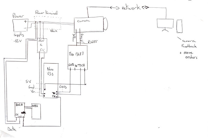
Could you make a drawing how everything is connected ? Where are the strong currents going ? especially the currents in the ground wires. You can make a drawing by hand and make a photo of it.

To solve this, you have to make small steps.
Remove all the power-hungry devices and check if you can communicate via RS-485 with the Nano. Then test only one Servo motor with a sketch that turns them to a few different angles. And so on.

the voltage arrives at 12V on a power terminal block, I have an output to an adjustable 12V transformer, set to 5V.
another output goes to the servos (therefore 12V).
The camera is powered upstream.

hi koepel, thank you for your involvement.

i use the library AX12A. it allow to control this servos without special shield (TX pin to data ax12a).
and here is a schematic, i hope it is readable for you.

i'm a newbie so i can't post files. i let you a wetransfer link for the PDF
Edit: i missed to draw ground between max13487 and the camera (ground power
supply->max13487)

i've done your test without servos and it's the same, always receive "0000000"
image

and i receive between 1 and 3 frames..
here is the code used in my nano

#include "AX12A.h"


/*-----( Declare Constants and Pin Numbers )-----*/
#define ID_Pan 1
#define ID_Tilt 2
#define RS485lTxControl 3   //RS485 Direction control 
#define RS485Transmit    HIGH   // not needed here, the servos attached to the arduino will not transmit any data to the Pelco-D controller  
#define RS485Receive     LOW
#define Pin13LED         13
#define DirectionPin (10u)
#define FauxBaudrate (1000000)
/*-----( Declare objects )-----*/
AX12A myservo;
/*-----( Declare Variables )-----*/
byte byteReceived[7];
int byteNumber = 0;
int byteSend;
int minPulse1     =  100;   // minimum servo position
int maxPulse1     =  212; // maximum servo position
int turnRate1     =  1;  // servo turn rate increment (larger value, faster rate)
int minPulse2     =  138;  // minimum servo position
int maxPulse2     =  178; // maximum servo position
int turnRate2     =  1;  // servo turn rate increment (larger value, faster rate)
/** The Arduino will calculate these values for you **/
int centerservoPAN;
int centerservoTILT;
int pulseWidth1;          // servo pulse width
int pulseWidth2;          // servo pulse width


void setup() {
  Serial.begin (9600);
  myservo.begin(FauxBaudrate, DirectionPin, &Serial);
  centerservoPAN = maxPulse1 - ((maxPulse1 - minPulse1)/2);
  centerservoTILT = maxPulse2 - ((maxPulse2 - minPulse2)/2);
  pulseWidth1 =  centerservoPAN;
  pulseWidth2 =  centerservoTILT;
  Serial.println("Arduino Serial Servo Control with Pelco D");
  Serial.println();
  
  pinMode(Pin13LED, OUTPUT);   
  pinMode(RS485lTxControl, OUTPUT);    
  digitalWrite(RS485lTxControl, RS485Receive);  // Init Transceiver   
  delay(10000);
  Serial.println("initialisation des moteurs");
  myservo.move(ID_Pan,pulseWidth1);
  myservo.move(ID_Tilt,pulseWidth2);
  Serial.println("ready");
}//--(end setup )---


void loop() {
//  if (!Serial.available())Serial.println("pas de co");
  if (Serial.available() > 0)  //Look for incoming serial data from Pelco-D controller
   {

    byteReceived[byteNumber ++] = Serial.read();    // Read received byte
    Serial.println(byteReceived[byteNumber], HEX);        // Show on Serial Monitor
    delay(10);
  
    if ( byteReceived[0] != 0xFF ) {byteNumber = 0;}   // When Byte 0 isn't 0xFF (Pelco 1st Byte) reset byteNumber to 0 preventing the serial port being blocked.
   }
    if ( byteNumber > 6 )                                 // process it
    {                 
      byteNumber = 0;                                 // ready for next time
      byte data = byteReceived[3];       // read the incoming byte:
      Serial.println(data, HEX);        // Show on Serial Monitor
      switch(data)
        {
          case 0x00 :  break;
          case 0x02 :  pulseWidth1 = pulseWidth1 - turnRate1;   ax12a.turn(ID_Pan, RIGHT, 100); break; // right
          case 0x04 :  pulseWidth1 = pulseWidth1 + turnRate1; ax12a.turn(ID_Pan, LEFT, 100); break; // left   
          case 0x10 :  pulseWidth2 = pulseWidth2 - turnRate1; myservo.move(ID_Tilt,pulseWidth2); break; // down
          case 0x08 :  pulseWidth2 = pulseWidth2 + turnRate1; myservo.move(ID_Tilt,pulseWidth2); break; // up
          case 0x14 :  pulseWidth1 = pulseWidth1 + turnRate1; myservo.move(ID_Pan,pulseWidth1); pulseWidth2 = pulseWidth2 - turnRate1; myservo.move(ID_Tilt,pulseWidth2); break; // left-up
          case 0x12 :  pulseWidth1 = pulseWidth1 - turnRate1; myservo.move(ID_Pan,pulseWidth1); pulseWidth2 = pulseWidth2 - turnRate1; myservo.move(ID_Tilt,pulseWidth2); break; // right-up
          case 0x0C :  pulseWidth1 = pulseWidth1 + turnRate1; myservo.move(ID_Pan,pulseWidth1); pulseWidth2 = pulseWidth2 + turnRate1; myservo.move(ID_Tilt,pulseWidth2); break; // left-down
          case 0x0A :  pulseWidth1 = pulseWidth1 - turnRate1; myservo.move(ID_Pan,pulseWidth1); pulseWidth2 = pulseWidth2 + turnRate1; myservo.move(ID_Tilt,pulseWidth2); break; // right-down
        }
        
        // stop servo pulse at min and max
        if (pulseWidth1 > maxPulse1) { pulseWidth1 = maxPulse1; }
        if (pulseWidth1 < minPulse1) { pulseWidth1 = minPulse1; }
        // stop servo pulse at min and max
        if (pulseWidth2 > maxPulse2) { pulseWidth2 = maxPulse2; }
        if (pulseWidth2 < minPulse2) { pulseWidth2 = minPulse2; }
       
    // print pulseWidth back to the Serial Monitor (uncomment to debug)
    Serial.println("Servo 1: ");
    Serial.println(pulseWidth1);
    Serial.println(" Servo 2: ");
    Serial.println(pulseWidth2);
    Serial.println("degrees");
   }
}

More links please !
Can you give a link to that "AX12A" library ?

yeah sure, escuse me:

here

I think the servo's are'nt the problem, at least not yet...

Your WeTransfer picture:

According to the schematic of the Arduino Nano, the VIN goes into a LM1117. There is a voltage drop of about 1V.
You can try to power the Nano with 5V applied to its 5V pin.

Splitting a serial port for two different things is okay. As long as the baudrate is the same.

Things that got my attention:

  • The Library does not work with every baudrate ? According to the introducation page. That seems very unreliable ! And the reason is unknown ?
  • The TX signal for the data for the servo motors is only valid with a good GND. That route for the GND from the Nano to the Servo motor seems to be very long.
  • The array size for byteReceived[7] is only seven. That scares me, can you make it 20 ?
1 Like

thank you, i will test it (gnd theory) and give you a feedback!

i know but i'd not found another library who works as well as this one :confused:

and there is with byteReceived[20], it's the same :confused:
image

Hey,

I've tried to change baudrate, according to the specs of the RS485-TTL converter, i've changed every baudrates to 500 kBps, connected the servo's GND for later and powered nano with the 5V pin.
always receive 0000000.

i asking myself about that, every baudrates are the same, however there is a weird print before "ready"
image

between "initialisation", and "ready" i'm ordering servo to move at their middle position.

 Serial.println("initialisation des moteurs");
  myservo.move(ID_Pan,pulseWidth1);
  myservo.move(ID_Tilt,pulseWidth2);
  Serial.println("ready");

with the dfrobot shield i did not receive that..

maybe comment servo's code to see if the library ax12a is the problem.

EDIT: i've removed ax12a library from my code and i receive the good orders!
Now we have to find a reliable library for ax12 without special shields .

It could still be the servo motors themself. Perhaps a lot of noise by the servo motors got into the serial lines. Perhaps there is a breadboard with bad contacts. Perhaps your wires are not well organized.

Here is a tutorial: https://forum.arduino.cc/t/common-ground-and-why-you-need-one/626215.
A star-grounding prevents a lot of problems, but sensors should not use the star-ground, and it has a few disadvantages.

Do you know how ground works ?
Let's say that the GND pin of the Arduino is the "real" ground. When connecting a wire of 1 meter to it, then there is no ground at the end of that wire. Because that wire is an antenna.
The current that flows into the servo motor returns via the ground wire to the power supply. That current through the ground wire can introduce a lot of noise in the whole circuit.

But all GND of every devices are now directly linked to the nano's GND, linked itself to the camera by the power terminal block :confused:

Also, i found this library who seems better reliable than the old one. But by using this file, i cannot operate the serial communication between RS485 converter and nano

That library is 10 years old, a lot of things have changed in the Arduino world in the last 10 years.

It is hard for me to say something useful about the ground or how that noise enters the serial signal without seeing and touching it. I'm not even sure that it is noise.
The RS-485 is mostly used with a ground signal to prevent unbalanced signals.
There could be so many things going on, I'm sorry, but I don't know what more I can say.

A few weeks ago, someone had a lot of trouble with an Arduino and electrical trains and cars. Such a circuit needs to build with grounding in mind.

ok, i will search on my way, thank you for your implication and i will update this topic if i find a solution :slight_smile:

hi everybody!

I finally found a great solution:

because of the servo motors and their library (ax12.h is the most reliable), it is impossible to make this system work with only one nano board.
The lonely solution i found is to use 2 of them in master/slave connection (I2C).

I am not a professional of electronics, but I found on this forum, the analog pins corresponding to this link (A4/A5).

I proceeded to the following assembly (sorry for french words):

splitting the code posted above in this way:

arduino master code:

#include <Wire.h>
#define RS485lTxControl 3   //RS485 Direction control 
#define RS485Transmit    HIGH   // not needed here, the servos attached to the arduino will not transmit any data to the Pelco-D controller  
#define RS485Receive     LOW

byte byteReceived[20];
int byteNumber = 0;
int byteSend;

void setup()
{
 Wire.begin(); // Rejoindre le bus I2C (Pas besoin d adresse pour le maitre)
 pinMode(RS485lTxControl, OUTPUT);
 digitalWrite(RS485lTxControl, RS485Receive);
 Serial.begin(9600);
}
void loop()
{
 if (Serial.available() > 0)  //Look for incoming serial data from Pelco-D controller
   {

    byteReceived[byteNumber ++] = Serial.read();    // Read received byte
    //Serial.println(byteReceived[byteNumber], HEX);        // Show on Serial Monitor
    delay(10);
  
    if ( byteReceived[0] != 0xFF ) {byteNumber = 0;}   // When Byte 0 isn't 0xFF (Pelco 1st Byte) reset byteNumber to 0 preventing the serial port being blocked.
   }
    if ( byteNumber > 19 )                                 // process it
    {                 
      byteNumber = 0;                                 // ready for next time
      byte data = byteReceived[3];       // read the incoming byte:
      Serial.println(data, HEX);        // Show on Serial Monitor
            switch(data)
        {
          case 0x00 : break;
          case 0x02 : Wire.beginTransmission(4);Wire.write(2);Wire.endTransmission(); break; // right
          case 0x04 : Wire.beginTransmission(4);Wire.write(4);Wire.endTransmission();break; // left   
          case 0x10 : Wire.beginTransmission(4);Wire.write(10);Wire.endTransmission();break; // down
          case 0x08 : Wire.beginTransmission(4);Wire.write(8);Wire.endTransmission();break; // up
          case 0x14 : Wire.beginTransmission(4);Wire.write(14);Wire.endTransmission();break; // left-up
          case 0x12 : Wire.beginTransmission(4);Wire.write(12);Wire.endTransmission();break; // right-up
          case 0x0C : Wire.beginTransmission(4);Wire.write(16);Wire.endTransmission();break; // left-down
          case 0x0A : Wire.beginTransmission(4);Wire.write(18);Wire.endTransmission();break; // right-down
        }
  

}
}

arduino slave code:

#include  <Wire.h>// Librairie pour la communication I2C
#include <ax12.h>
#define ID_Pan 1
#define ID_Tilt 2
//#define DirectionPin (10u)
//#define FauxBaudrate (1000000)
int centerservoPAN;
int centerservoTILT;
int pulseWidth1;          // servo pulse width
int pulseWidth2;          // servo pulse width
int minPulse1     =  -150;   // minimum servo position
int maxPulse1     =  150; // maximum servo position
int turnRate1     =  1;  // servo turn rate increment (larger value, faster rate)
int minPulse2     =  -150;  // minimum servo position
int maxPulse2     =  150; // maximum servo position
int turnRate2     =  1;  // servo turn rate increment (larger value, faster rate)

AX12 servo_pan(1);
AX12 servo_tilt(2);

void setup()
{

  AX12::init(1000000);
  centerservoPAN = maxPulse1 - ((maxPulse1 - minPulse1) / 2);
  centerservoTILT = maxPulse2 - ((maxPulse2 - minPulse2) / 2);
  pulseWidth1 =  centerservoPAN;
  pulseWidth2 =  centerservoTILT;
  pinMode(13, OUTPUT);
  delay(10000);
  angle(servo_pan, pulseWidth1);
  angle(servo_tilt, pulseWidth2);
  digitalWrite(13, HIGH); // servo "ready" indicator


  Wire.begin(4); // Rejoindre le bus à l'adresse #4
}
void loop()
{
  Wire.onReceive(receiveEvent); // launch a function while receiving data
  delay(10);

}
void receiveEvent(int howMany)
{
  int x = Wire.read(); // receive a number
  switch (x)
  {
    case 0 :  break;
    case 2 :  pulseWidth1 = pulseWidth1 - turnRate1;  angle(servo_pan, pulseWidth1); break; // right
    case 4 :  pulseWidth1 = pulseWidth1 + turnRate1; angle(servo_pan, pulseWidth1); break; // left
    case 10 :  pulseWidth2 = pulseWidth2 - turnRate1; angle(servo_tilt, pulseWidth2); break; // down
    case 8 :  pulseWidth2 = pulseWidth2 + turnRate1; angle(servo_tilt, pulseWidth2); break; // up
    case 14 :  pulseWidth1 = pulseWidth1 + turnRate1; angle(servo_pan, pulseWidth1); pulseWidth2 = pulseWidth2 - turnRate1; angle(servo_tilt, pulseWidth2); break; // left-up
    case 12 :  pulseWidth1 = pulseWidth1 - turnRate1; angle(servo_pan, pulseWidth1); pulseWidth2 = pulseWidth2 - turnRate1; angle(servo_tilt, pulseWidth2); break; // right-up
    case 16 :  pulseWidth1 = pulseWidth1 + turnRate1; angle(servo_pan, pulseWidth1); pulseWidth2 = pulseWidth2 + turnRate1; angle(servo_tilt, pulseWidth2); break; // left-down
    case 18 :  pulseWidth1 = pulseWidth1 - turnRate1; angle(servo_pan, pulseWidth1); pulseWidth2 = pulseWidth2 + turnRate1; angle(servo_tilt, pulseWidth2); break; // right-down
  }
  // stop servo pulse at min and max
  if (pulseWidth1 > maxPulse1) {
    pulseWidth1 = maxPulse1;
  }
  if (pulseWidth1 < minPulse1) {
    pulseWidth1 = minPulse1;
  }
  // stop servo pulse at min and max
  if (pulseWidth2 > maxPulse2) {
    pulseWidth2 = maxPulse2;
  }
  if (pulseWidth2 < minPulse2) {
    pulseWidth2 = minPulse2;
  }
}

byte angle(AX12 ax, int a)
{
  return ax.writeInfo(GOAL_POSITION, map(a, -150, 150, 0, 1023));
}

i have just one little problem, not every orders are received, but it's problably caused by my ip camera.

I'm very glad that it works better, but I don't understand why it didn't work with a single Arduino board.

A few notes:

You should have pullup resistors of 2k2. Normal is 4k7 or 10k, but I prefer to lower the impedance of the I2C bus for your project.

The Wire.onReceive() should be called just once in setup() after Wire.begin(4). It sets the handler which is called from an interrupt routine when all the data is received.

Since the Wire.onReceive() is running in a interrupt routine, keep it as small and as short as possible. Do the processing in the loop().
Therefor you should pass on the information to the loop(). When you do that, the variables must be volatile, so the compiler knows that they can be changed in a interrupt.

volatile byte data;
volatile bool newData = false;

void loop()
{
  if( newData)
  {
    switch( data)
    {
      case 0 : break;
      ...
    }
    newData = false;
  }
}

void receiveEvent( int howMany)
{
  if( howMany == 1)         // extra safety check, expecting one byte
  {
    data = Wire.read();     // store the data
    newData = true;         // set flag to notify the code in the loop()
  }
}

The above code assumes that the data is processed before a new byte arrives.
With a ringbuffer between the onReceive handler and the loop(), every byte will be processed.
There is an alternative in between, by making a copy of the data. That almost a buffer of one byte.

volatile byte data;
volatile bool newData = false;
volatile byte error = 0;

void loop()
{
  if( error > 0)
  {
    Serial.print( "Too much I2C data input ! Errors: ");
    Serial.println( error);
    error = 0;
  }

  if( newData)
  {
    byte dataCopy = data;   // make a copy.
    newData = false;        // release the 'data' variable immediately

    switch( dataCopy)       // Be sure to use the copy from now on
    {
      case 0 : break;
      ...
    }
  }
}

void receiveEvent( int howMany)
{
  if( howMany == 1)     // extra safety check, expecting one byte
  {
    if( newData)        // is the data variable still occupied ?
    {
      // The loop() can not keep up with the incoming data.
      // The previous data was not yet processed in the loop().
      error++;
    }
    else
    {
      // The data variable was already released in the loop().
      // It is ready to store new data into it.
      data = Wire.read(); // store data
      newData = true;     // set flag
    }
  }
}
1 Like

This topic was automatically closed 120 days after the last reply. New replies are no longer allowed.