Newbie here. I am building a model railway layout and have built the control panel. I have 16 signals on the layout, and mimicked on the control panel. There are 4 banks of 4 DPDT switches with corresponding red & green LEDs which mimic the LEDs on the signal heads. The LEDs on the panel are ALL wired in parallel with "K" leg going to -ve and the "A" leg going through the switches. All in all there are 68 LEDs - yes 68! I have calculated that I need a 7.1324Ohm resistor, however the wattage of the resistor is 13.192 Watts! I know 16 x 4 does not equal 68! But here are master switches controlling street lighting, buildings, etc. That is where the other 4 LEDs come into play.
BTW the voltage is 12VDC. I also have point controls - turnouts to those in Nth America - that will be supplied from 15VDC. Would I be better off using 4 sets of resistors - 1 on each bank of switches. Online calculator tells me that the resistor value would be 30.1325Ohms @ 3.104 Watts and would it be better to have the resistor before or after the LED?
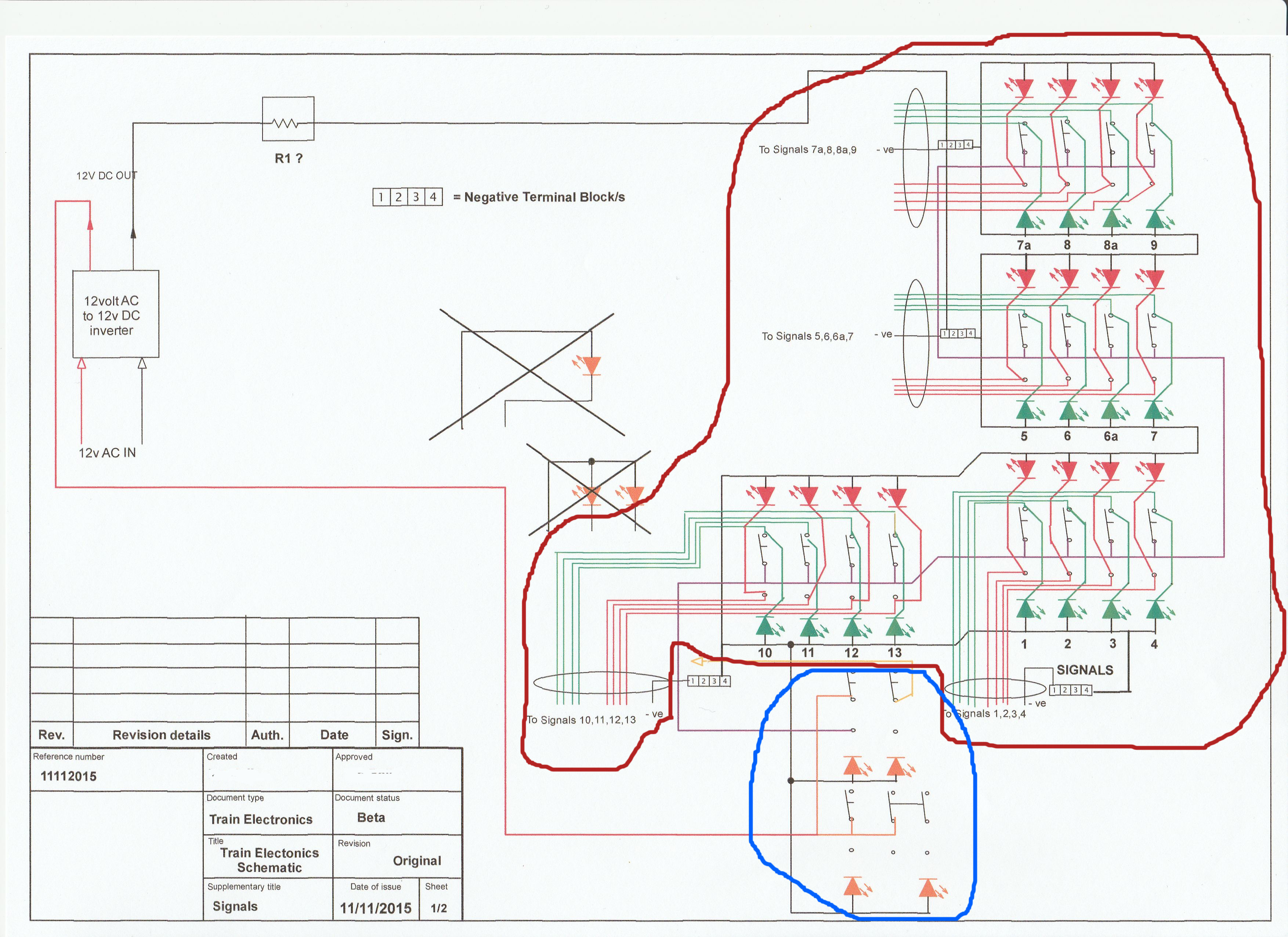
I am attaching files of the control panel and the wiring diagram. On both files the bank of 16 switches are circled in RED and the 4 extra switches are circled in BLUE.
They are not wired in parallel if they are each connected to a switch. Parallel is when all anodes are connected and all cathodes are connected. They all light together.
You cannot use one series R for the lot. If you only have one LED on then the R is far too small. You need a series R for each LED.
If there are groups that come on together, they should also have their own R to distribute the current evenly if wired in parallel. Better still, use series/parallel strings.
ianb26:
Ok thanks for your reply. The second attachment didn't go through so I will send it with this post. I will digest what you said, and get back to you.
Thanks again
Third time lucky. I decreased the size of the file, so hopefully it will go through now
Really hard to see whats going on in that diagram but as far as I can tell you have 16 signals each with a "red" and "green" input, usually fed from 12V. What you want is to have a pair of red/green LEDs on the switchboard to mirror the state of the signals.
In that case, you would need something like the attached circuit for each signal/switch/LED pair combination
This makes the assumption that both red & green LEDs have a similar forward voltage (typically 2.2 - 2.4v) so for 12V and 20mA LED current you would need a resistor of (12 - 2.4)/0.02 = 480 ohms (nearest value of 470 ohms would be fine, or 510 if you want to play really safe)