Hi all,
I have a NPN proximity sensor with the rating voltage 6 - 36 DC (https://www.amazon.co.uk/gp/product/B07SD9VYDH/ref=ppx_yo_dt_b_asin_title_o05_s00?ie=UTF8&psc=1)and wanted to connect to the input PIN of Arduino Yun.
The proximity sensor has 3 wires: blue (ground), brown (vcc), black(signal). Since it is NPN NO type of proximity sensor, the signal voltage is equal to the vcc when it is normally open.
I read from the datasheet, the input PIN of Arduino YUn operates at 5 volts. Meanwhile,the ouput voltage (signal) from proximity sensor will be more than 5 volt. How can I read the signal from sensor that is more than 5 volts using Arduino?
What I've tried:
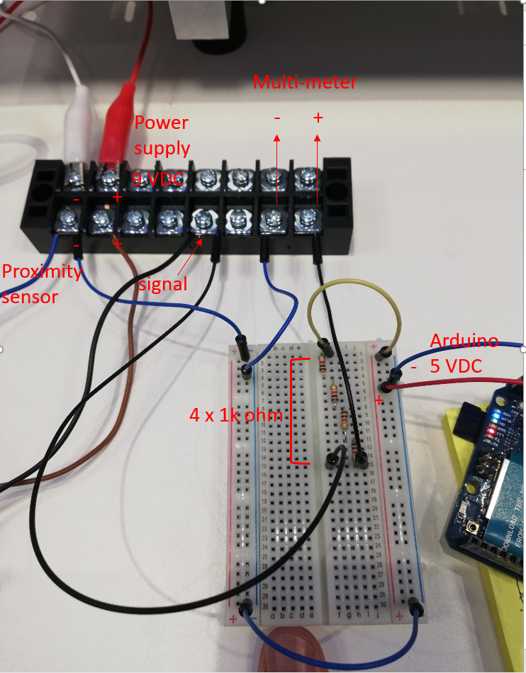
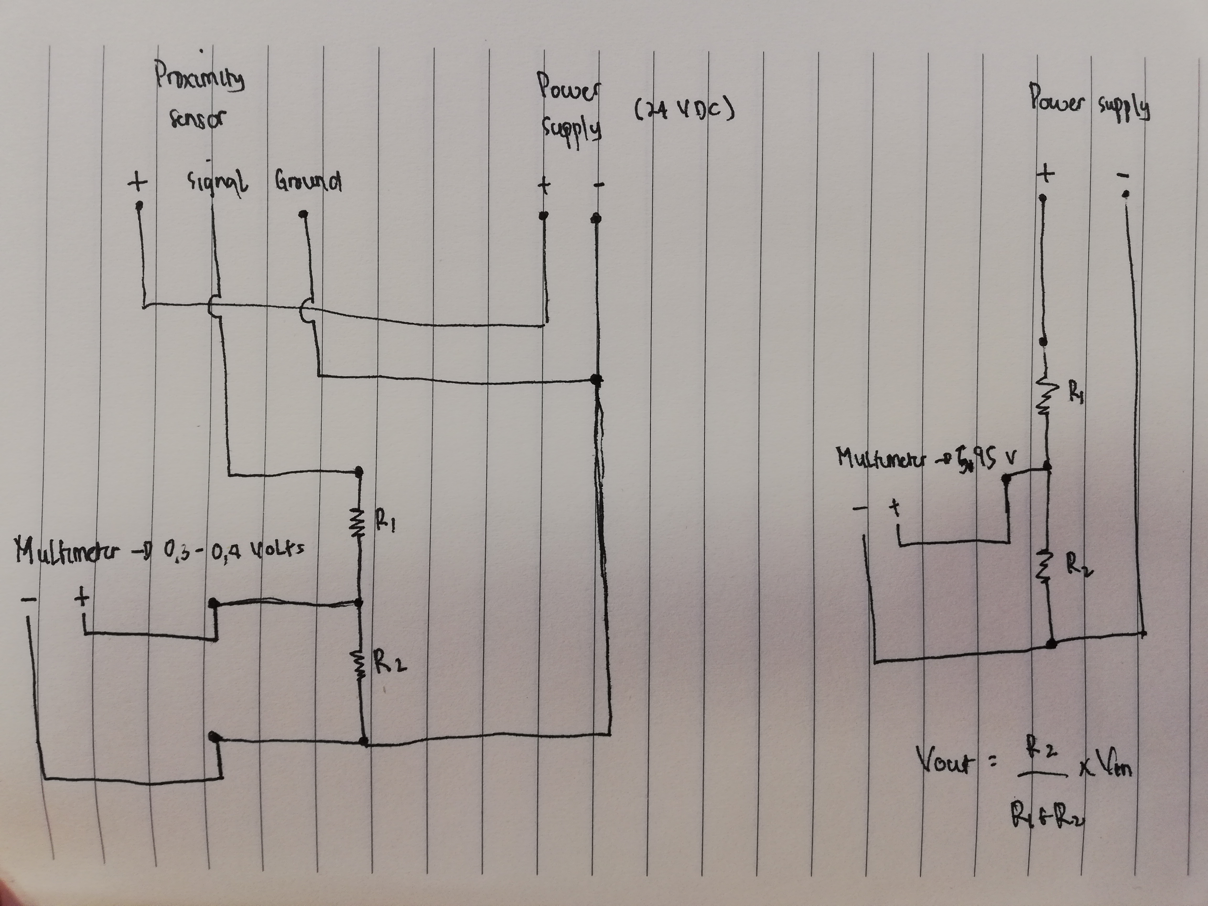
- hooking up signal wire to voltage divider and step it down -> the voltage that I read with multimeter is 0.3 -0.5 volts. But, when I hook up the output voltage from power supply directly, it gives the stepped down voltage as it should according to the formula.
The wiring schematic is on this below link. R1 is 1k ohm and R2 is 330 ohm.

Note that the point is why voltage divider does not work with voltage from signal and it works from power supply?
- hooking up signal from sensor to buck converter to step the voltage down -> same as in voltage divider case. The voltage reading works correctly from power supply but not from signal voltage from sensor.
I have a feeling that I might miss some underlying principle here. Can anybody tell me what I am missing here?
Thanks
Please read "Read this before posting a programming question" at the top of the forum.
You need to be a little lot more specific about your problem:
Post your sketch (code), schematic in CAD or a picture of a hand drawn circuit in jpg or png- (not a pretty Fritzing drawings), error messages, etc.
"Meanwhile, sensor ouput from proximity will be more than 5 volt. How can I read the sensor ouput more than 5 volts using Arduino?"
What sensor? If the output is analog as your question implies, then use Analog input with appropriate voltage divider to keep from exceeding the Analog pin limits.
Hi Steve,
Thanks for the reply. I have added more information to my question. Hope it clarifies thing. Also the output is digital signal.
The schematic on the Heschen website makes absolutely no sense:

But from your schematic, I am guessing that you have figured out the connections. So, the output is connected to the +V input, and that is what you want to detect. Odd configuration. Is that what you are seeing when you measure the voltage of the "Signal" wire?
If the 24V supply is stable (not likely to go above 24V), then a simple voltage divider on the sensor output should work.
The resistors you selected gives an output voltage of 6V, which could fry your Arduino. Better to aim lower. Use 10K for R1 and 2.4K for R2 and you should see 4.7V which is OK for a logic high.
Hi Steve,
So, the output is connected to the +V input, and that is what you want to detect. Odd configuration. Is that what you are seeing when you measure the voltage of the "Signal" wire?
Yes, this is what I do and the output voltage is the same as vcc when I measure with Multimeter.
The resistors you selected gives an output voltage of 6V, which could fry your Arduino. Better to aim lower. Use 10K for R1 and 2.4K for R2 and you should see 4.7V which is OK for a logic high.
That's right. I am using buck converter to step down the voltage of power supply before hooking up with proximity sensor. In this way, I still can get the output voltage below 5 volts while maintaining the values of R1 and R2.
then a simple voltage divider on the sensor output should work.
Indeed, this is what I thought. Why voltage divider can step down the voltage from power supply but not working correctly with voltage supplied by sensor output (signal). This is still a mystery for me.
Surprisingly, I found the video of someone hooking up 9 volts output sensor (power supply 9 VDC) directly to input pin arduino without any problem. But, I don't yet dare to try it this way.
The Vin pin on the Arduino, as explained in the rambling video you linked to, is connected to the barrel connector, which is rated to 12 volts.
The I/O pins are rated for 5.5 V Max. Any more and you risk smoking the input pin.
If you are using the bucking voltage converter to get the power down to 5V (which you don't show on your schematic), then you don't need the voltage divider.
Hi,
What is the exact part number written on your sensor?
Your links and part number show a 2 WIRE sensor not a 3 WIRE.
Thanks.. Tom.... 
Hi Steve,
If you are using the bucking voltage converter to get the power down to 5V (which you don't show on your schematic), then you don't need the voltage divider.
Yes. you are right. However, in my case I have a proximity sensor and Arduino which have different rating voltage. So, I need to power up both devices with different voltage sources which introduces the need of converting the output from proximity sensor to the operating voltage of Arduino input PIN. The problem being faced here is I manage to step down the voltage from power supply to safely power up Arduino. But, with the same approach, I haven't managed to step down the output voltage from sensor to be hooked up safely to Arduino input PIN.
Hi Tom,
Thanks for your reply. I have edited the link in my first post.
Hi,
Your 3 wire sensor is NPN output, OPEN COLLECTOR.
This is so you can operate the sensor on a different power supply to the controller that will be connected to the signal output.
The diagram below should demonstrate how you wire it up,
Use a DMM to measure the output voltage with respect to GND, and operate the sensor.
This is a standard industrial sensor configuration, the data has been stuffed a round by ill informed sellers and distributors.
Tom..
Hi Tom,
Just when I was thinking about the pull-up resistor for the NPN output, you replied with the schematic for that.
However, after following up the schematic, I do not get the measurement of signal voltage as I thought it would be.
The wiring that follows the schematic is on the link below

I expect that the output voltage would be the pull-up voltage (5 VDC provided by Arduino). But, the voltage that I measured was 7.5 VDC. I also did the wiring with the new and the same sensor and the result is the same.
I think I am needing Aspirin now 
")