I am trying to make 5 solenoid valves of this type to work independent of each other and to just do on/off motion such that I can control it via bluetooth through a phone. The valves need to stay open for a decent amount of time (max 15 minutes) when requested to do so. I have a Fritzing diagram that I wanted to see if it would work for this possible scenario. I also have some code that I wanted to use for this as well. I will give the list of materials that I think I will use for this design. Please excuse the messy layout and any errors on the circuitry/code, I have very little knowledge of circuits.
List:
Arduino Uno Rev3
HiLetgo HC-05 Bluetooth module
ELEGOO 8 channel DC 5V relay module
11.1V 5200mAh Li-ion battery pack
ALso, what kind of diodes and fuse should I use? I have them included in the circuit diagram to not have any EMF problems or help prevent circuit heat issues
Thanks for the perfect posting of the code!
Forget powering the relays from the controller 5 volt. The onboard converter will get overheated and damaged.
Forget running all relay coil current through a breadboard. It's designed for mA signals, not the power of relay coils.
Fritzings are not welcome. Please create proper schematics with pin designations.
Datasheets for valves and relays are alse requested.
I would recommend you use the term 'On or Off' in place of HIGH or LOW. Simply define them at the start of your code. If you switch machines or the hardware changes only those lines would need to change and your code would be more readable.
As @Railroader asked post an annotated schematic. Your frizzy picture may be OK for somebody that has the parts and is wiring it but it is useless when trying to troubleshoot.
Guidelines for Effective Troubleshooting:
Posting an annotated schematic of your circuit is crucial for us to help you effectively. Your schematic should clearly show all connections, power sources, components, and ground connections. Highlight any logic wires longer than 10 inches (25 cm), and provide links to technical information for all hardware components, including motors, shields, and Arduinos. Be sure to include component values, model numbers, and details of all power supplies (e.g., USB power). Posting your code using the forum’s code tags will also be very helpful.
Why This Matters:
Many issues arise from connection or power problems that could be easily identified with a well-drawn schematic and proper technical information. Often, users without schematics spend time troubleshooting through trial and error, which can be frustrating and time-consuming. When a detailed schematic is provided, solutions are often found within a day.
Creating Schematics:
What to Include: Show all connections, highlight any potential issues (like long wires), and provide links to component datasheets or technical documentation. This helps us understand your setup and diagnose problems quickly.
Acceptable Formats: Hand-drawn schematics are fine as long as they are clear and readable. High-quality photos of your circuit can also be helpful.
Schematic Capture Software: Tools like KiCad are popular for creating schematics. KiCad is free and works on Linux, macOS, and Windows. It has a learning curve, but many free online resources can help you get started. KiCad also includes features like a 3D viewer and an integrated SPICE simulator for verifying designs.
Helpful Resources on Schematics:
What is a Schematic Diagram?
How to Read a Schematic
How to Read a Schematic (Video)
Tips for Using KiCad or Similar Tools:
Start Simple: Begin with small designs to get comfortable with the tool.
Customize Components: If you can’t find a specific part, edit existing components to fit your needs.
Verification: Use the SPICE simulator and electrical rules checker in KiCad to validate your designs.
Providing a complete schematic with detailed technical links will make troubleshooting easier and faster, helping you find solutions efficiently. Let us know how we can assist further!
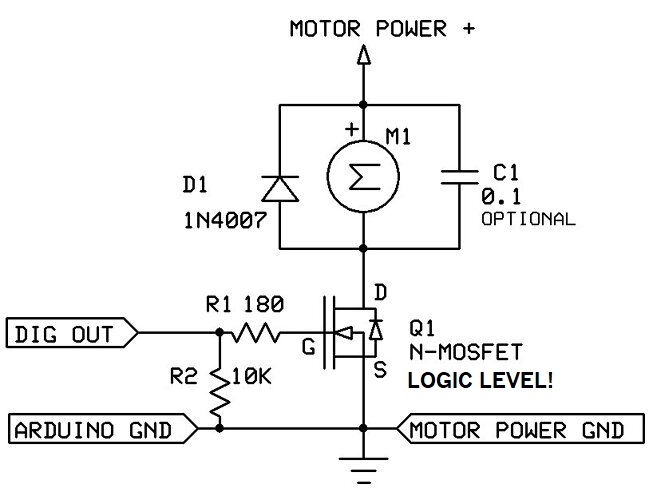
First, figure out how to get one valve to work. You don't need a relay for that, just the circuit below (five such circuits will control five valves). The diode is required, and must be installed exactly as shown, across the motorized valve terminals.
The motor power supply must provide 9 to 24V DC at 5 watts.
In the matter of comms, your wiring is quite sufficiently readable, but does not agree with your code. Bluetooth is wired for software serial operation but you have no code to drive it, and thus have no chance of it working. The code IS, ostensibly, set up to work with serial input, so you CAN run it by feeding dummy data from the keyboard, and I would submit it is actually a sensible aproach. Once everything is deemed satisfactory, you may then relocate Bluetooth to serial pins 0,1, no change to code required, but remember that bluetooth must be disconnected while you are uploading.
The intention of what I assume is a tantalum is far from clear. Perhaps learning how to rotate a Fritz might be in order... The same applies to the batteries.....
The motor power supply is just too hard to read because of the trace colours but it appears you are switching to ground, in which event, taking the wires to battery negative just like all those on battery positive would be a safer approach.