master arduino code
#include <SPI.h> // Include SPI library
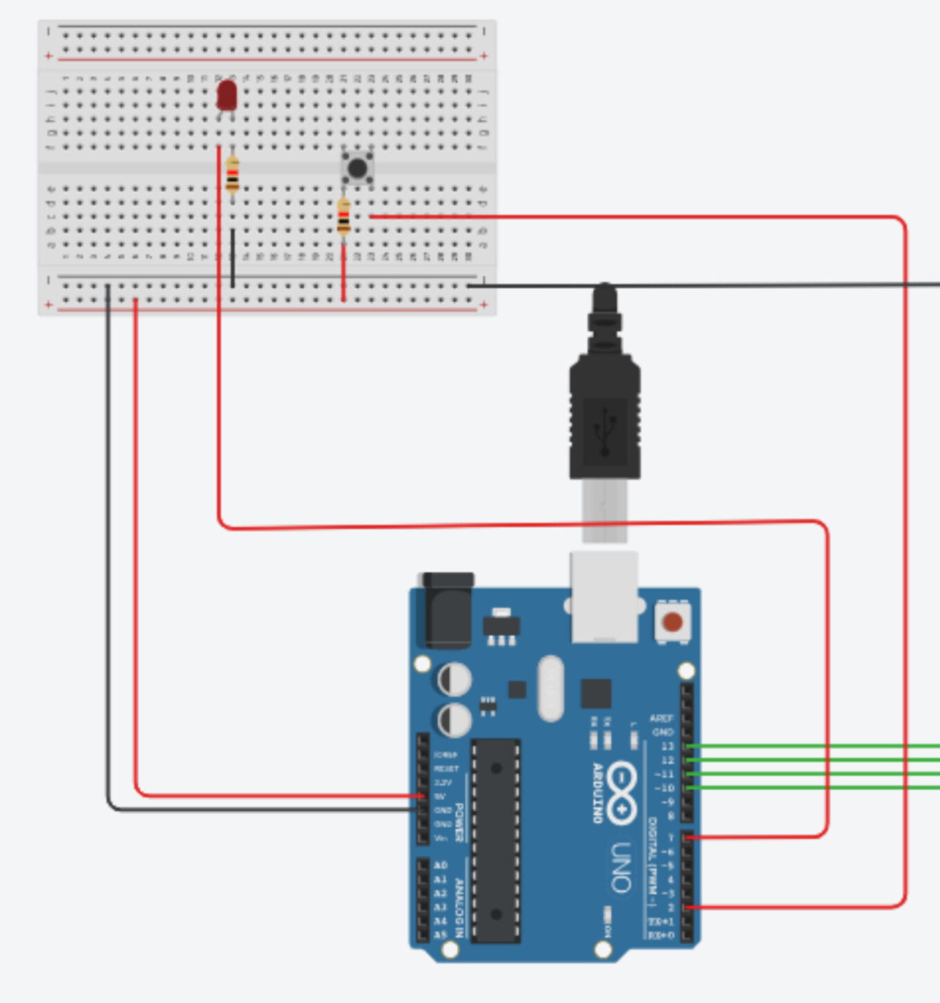
#define LED 7 // LED connected to Pin 7
#define BUTTON 2 // Button connected to Pin 2
int buttonState;
int x;
void setup() {
Serial.begin(115200); // Start Serial communication
pinMode(BUTTON, INPUT); // Set button pin as input
pinMode(LED, OUTPUT); // Set LED pin as output
SPI.begin(); // Start SPI as Master
SPI.setClockDivider(SPI_CLOCK_DIV8); // Set SPI clock to 2MHz (16MHz/8)
digitalWrite(SS, HIGH); // Deselect the Slave by setting SS HIGH
}
void loop() {
byte masterSend, masterReceive;
// Read the button state
buttonState = digitalRead(BUTTON);
// Set value to send based on button state
if (buttonState == HIGH) {
x = 1;
} else {
x = 0;
}
// Start communication with the Slave
digitalWrite(SS, LOW); // Select the Slave
masterSend = x;
masterReceive = SPI.transfer(masterSend); // Send and receive data
digitalWrite(SS, HIGH); // Deselect the Slave
// Set LED state based on the received value
if (masterReceive == 1) {
digitalWrite(LED, HIGH); // Turn on LED
Serial.println("Master LED ON");
} else {
digitalWrite(LED, LOW); // Turn off LED
Serial.println("Master LED OFF");
}
delay(1000); // Wait for 1 second
}
slave arduino code
#include <SPI.h> // Include SPI library
#define LED 7 // LED connected to Pin 7
#define BUTTON 2 // Button connected to Pin 2
volatile boolean received;
volatile byte slaveReceive, slaveSend;
int buttonState;
int x;
void setup() {
Serial.begin(115200); // Start Serial communication
pinMode(BUTTON, INPUT); // Set button pin as input
pinMode(LED, OUTPUT); // Set LED pin as output
pinMode(MISO, OUTPUT); // Set MISO as output for SPI
SPCR |= _BV(SPE); // Enable SPI in Slave mode
SPI.attachInterrupt(); // Enable SPI interrupt
received = false; // Reset received flag
}
ISR(SPI_STC_vect) {
slaveReceive = SPDR; // Read the received data
received = true; // Set received flag
}
void loop() {
if (received) { // Check if data is received
received = false; // Reset received flag
// Set LED state based on received value
if (slaveReceive == 1) {
  digitalWrite(LED, HIGH);   // Turn on LED
  Serial.println("Slave LED ON");
} else {
  digitalWrite(LED, LOW);    // Turn off LED
  Serial.println("Slave LED OFF");
}

// Read the button state
buttonState = digitalRead(BUTTON);

// Set value to send based on button state
if (buttonState == HIGH) {
  x = 1;
} else {
  x = 0;
}

slaveSend = x;
SPDR = slaveSend;            // Send data back to Master
}
delay(1000); // Wait for 1 second
}

help me to identify the issues.
It doesnt show anything in serial monitor