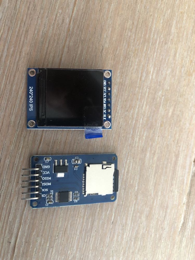
TFT Display (description from Aliexpress: New IPS 1.3 inch 3.3V 12PIN SPI HD Full Color TFT Display Screen ST7789 Drive IC 240*2) As you can see in the description, the display is SPI, but the pins are labeled somewhat strangely. The pins on that module are GND VCC SCL SDA RES DC BLK. SDA and SCL would suggest that it is I2C.
SD Card Reader SPI with standard pins SCK MISO MOSI CS
Has anyone dealt with such a display? How to connect these parts so that they function together. Once, right after purchase, I connected this display and I know it worked. I probably had to do it by trial and error method because back then I didn't even know what SPI and I2C were
It seems that the display is missing one pin.
SCL - SCK
SDA - MOSI MISO?
DC - CS?
Help!
Nothing specific. But because SD cards and most IPS LCD displays are 3.3V devices, and both require large amounts of dynamic/RAM memory, I would choose a 3.3V Arduino with lots of dynamic/RAM memory, and an SD card and LCD that don't contain level shifters, and have all the expected pins.
But still the SD card reader would not allow to share SPI, so no real solution for me. Funny enough I am sure I was connecting both components to 5v Arduino without level shifters. I powered it from 3,3V pin but others pins were connected directly and not through level shifters. The components worked fine and did not get damaged. I cannot say the same for the lora module I connected to 5v in one of my projects:)
I have Arduino r4 WIFI board with much more resources but there I would probably run into compatibility issues with libraries and RENESAS MC
So it look like to create a project that both components coexist will be difficult. Alternatively what other options to store bitmaps for that display externally do I have. I looked at eeprom memory but they are too small.
I was suggesting a different SD card reader module, that doesn't have level shifters and will share the bus.
It may be possible to use a circuit between your SD card module and the Arduino to allow it to share the bus.
The problem with your SD card reader is that the level shifter chip used, and the way it has been connected, means that the MISO pin doesn't disconnect from the SPI bus when the SD card is not selected via it's CS pin. Because of that, it interferes with the MISO signals of other SPI devices. I have seen fixes for that which may be as simple as a resistor (I don't know how well they work) or a buffer chip which can disconnect the SD card MISO signals when required.
So If I find SD card reader without level shifter I should be ok on the sd card reader side. But How do I get around the lack of CS pin on the TFT display. How wpould i conenct it together with the sd card reader so that the both components work
As @rsmls suggested, check in case it is actually an i2c device. But I doubt that it is. I2c bus is probably too slow for a device such as this. And i2c devices would not have a DC pin. On the other hand, SPI should have a CS pin, but this one apparently doesn't.
The DC pin tells the display if the data it is receiving is image Data or a Command.
The BLK pin is the cathode of the lcd's backlight, I suspect.
I suspect that this display was badly designed, much like the SD card module, because the designer assumed it will not need to share the i2c bus.
Again, with additional circuitry, it could be made to work, if that is what you want to do.
I think a single 74hc125 might be able to fix the problems with both modules. It is a quad buffer chip, with each buffer having an output enable control.
One of these buffers could fix the problem with the SD card module, by disabling the MISO signal from the module when it is not selected. Two more buffers could disable the SDA/MOSI and SCL/SCK inputs of the LCD module, in effect giving the module it's missing CS pin.
This is great that the fix exist but unfortunately this would be way over my head. Looks like my project is dead in the water. Is there any other way to feed data 8Bitmap images to this display from external data source?
Yes, use components that don't have weird design flaws and peculiarities and have the capabilities your project needs. But how can you, as a beginner, know what those are? If only there was a forum where you could ask such questions before spending your money...
The only consolation is that I want to use the components I already have . I didn't buy them specifically for this project. I looked at this buffer chip. this is super interesting stuff. buy I fear that I would invest a lot of time to figure this out and it will still not work. So how would the code work in terms of enabling and disabling the channels when reading bitmap dat from the SD card. Would I enablechannal for SD card to read a byte of data from the SD card. Then disable that channal and open the one for the display. And doing it byte at the time
The display is an SPI device with the clock and data lines mislabeled to appear as I2C lines. The CS line is hard wired to ground so the SPI interface cannot be shared. I finally found this article that got mine working.
Also would you be able to point me to the two modules in any online shop that would do the trick for me. I check Aliexpress and majority of TFT display on offer have the same weird pins.
@oldcurmudgeon@rsmls What do you think of my idea from post #9? I hope that could give the LCD the CS pin it is missing, enabling sharing the SPI bus. Buffers would be placed on MOSI and SCK lines, and the enable pins would be commoned and these would become the new CS line for the display. Voltage dividers between the buffer outputs and display could adapt the signals to 3.3V levels.
For the SD card module, a third buffer would be used on the MISO line and the enable pin for that buffer connected to the SD card CS pin, enabling that device to share the bus also. But maybe this won't be needed, since the LCD has no MISO pin...
@Dziubym have you decided which type of arduino you will use and tested it's performance with the LCD?
Most Arduino would not have sufficient dynamic memory/RAM to have a memory buffer for a display with so many colour pixels, so I would expect it to use a read-modify-write approach, but it can't do that without a MISO pin... So will this library work only with Arduino with large amounts of RAM?
In general, I think you can use some kind of GPIO controlled switch to select between either SPI device. I was thinking along the lines of CMOS switches, but there are several approaches that would work.
This drives me crazy. I've also seen the same problem on industrial devices that are north of $1,000. At that price you'd think they could design them properly.