Connection problem two I2C bus with different address

I don't know your board and I don't know the ESP32 platform well. The MCU in question has 2 i2c peripherals, i.e. inside the chip there are 2 separate buses, ok.
The standard wire is configured by default on pins 21(SDA) and 22(SCL).

  Serial.println(SDA);
  Serial.println(SCL);

While the Wire1 object exists but is not configured, to configure it I use:

  // 26(SDA1) and 27(SCL1) but other pins can be used.
  bool res = Wire1.begin(26, 27, 100000);
  Serial.print("res = ");
  Serial.println(res);

Ok, I don't use U8x8lib.h but the following lib from Adafruit:

I create my oled object like this:

#define OLED_RESET     -1 // Reset pin # (or -1 if sharing Arduino reset pin)
#define SCREEN_ADDRESS 0x3C ///< See datasheet for Address; 0x3D for 128x64, 0x3C for 128x32
Adafruit_SSD1306 oled(SCREEN_WIDTH, SCREEN_HEIGHT, &Wire1, OLED_RESET);

Note the &Wire1 argument

I initialize and use the oled object like this:

// nel setup()
    if(!oled.begin(SSD1306_SWITCHCAPVCC, SCREEN_ADDRESS)) {
        Serial.println("SSD1306 allocation failed");
        for(;;); // Don't proceed, loop forever
  }
  oled.clearDisplay();
  for(int16_t i=0; i<oled.width(); i+=4) {
    oled.drawLine(0, 0, i, oled.height()-1, SSD1306_WHITE);
    oled.display(); // Update screen with each newly-drawn line
    delay(1);
  }

So I use the second hardware device which is much more
fast and configurable compared to implementation of the I2c protocol via software.

I only now notice that the constructor you call is the following:

U8X8_SSD1306_128X64_NONAME_SW_I2C(uint8_t clock, uint8_t data, uint8_t reset = U8X8_PIN_NONE) 

3 arguments in this order: SCL, SDA, RESET_PIN

You wrote:

U8X8_SSD1306_128X64_NONAME_SW_I2C u8x8(18, 17, 21);

Then: 18(SCL), 17(SDA), 21(RESET)

But pin 21 should be SDA, in my case it is.

However I would try to use the following constructor:

U8X8_SSD1306_128X64_NONAME_2ND_HW_I2C(uint8_t reset = U8X8_PIN_NONE)

So you create your u8x8 object like this:

U8X8_SSD1306_128X64_NONAME_2ND_HW_I2C u8x8();

[Italiano]
Io non conosco la tua scheda e conosco non bene la piattaforma ESP32. La MCU in questione ha 2 periferiche i2c, cioè dentro il chip ci sono 2 bus separati, ok.

La wire standard è configurata di default sui pin 21(SDA) e 22(SCL).

  Serial.println(SDA);
  Serial.println(SCL);

Mentre l'oggetto Wire1 esiste ma non è configurato, per configurarlo io uso:

  // non sono obbligato ad usare 26(SDA1) e 27(SCL1)
  bool res = Wire1.begin(26, 27, 100000);
  Serial.print("res = ");
  Serial.println(res);

Ok, io non uso U8x8lib.h ma quella di Adafruit:

Creo il mio oggetto oled così:

#define OLED_RESET     -1 // Reset pin # (or -1 if sharing Arduino reset pin)
#define SCREEN_ADDRESS 0x3C ///< See datasheet for Address; 0x3D for 128x64, 0x3C for 128x32
Adafruit_SSD1306 oled(SCREEN_WIDTH, SCREEN_HEIGHT, &Wire1, OLED_RESET);

Nota l'argomento &Wire1

Inizializzo e uso l'oggetto oled così:

// nel setup()
    if(!oled.begin(SSD1306_SWITCHCAPVCC, SCREEN_ADDRESS)) {
        Serial.println("SSD1306 allocation failed");
        for(;;); // Don't proceed, loop forever
  }
  oled.clearDisplay();
  for(int16_t i=0; i<oled.width(); i+=4) {
    oled.drawLine(0, 0, i, oled.height()-1, SSD1306_WHITE);
    oled.display(); // Update screen with each newly-drawn line
    delay(1);
  }

In questo modo uso la seconda periferica hardware che è molto più
rapida e configurabile di una implementazione del protocollo I2c via software.

Noto solo ora che il costruttore che richiami è il seguente:

U8X8_SSD1305_128X32_NONAME_SW_I2C(uint8_t clock, uint8_t data, uint8_t reset = U8X8_PIN_NONE)

3 argomenti in questo ordine: SCL, SDA, RESET_PIN

Tua hai scritto:

U8X8_SSD1306_128X64_NONAME_SW_I2C u8x8(18, 17, 21);

Allora : 18(SCL), 17(SDA), 21(RESET)

Ma il pin 21 dovrebbe essere SDA, nel mio caso lo è.

Comunque io proverei ad usare il costruttore seguente:

U8X8_SSD1306_128X64_NONAME_2ND_HW_I2C(uint8_t reset = U8X8_PIN_NONE)

Quindi crei il tuo oggetto u8x8 in questo modo:

U8X8_SSD1306_128X64_NONAME_2ND_HW_I2C u8x8();

Ciao.
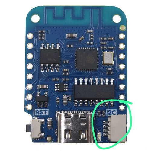
@Maurotec I read on the net that u8g2 and previous version (u8x8 ) Is most loved by users as being easier and powerful, It contains a lot of fonts which allows you tò print symbols also in an easier way. I can't say the same for adafruit library as I used It for simple task only.
Regarding MCU, I don't know what It Is, i only have a nodeMCU from lonin wemos but i never used as I don't know how powerful It Is.
I switched to a wemos d1 mini as i find It easier to manage. Probably it's not a good choise, but actually It works and I found easier to connect to Arduino iot Cloud (esp32-s3 Is not yet allowed).
I probably don't need a war machine to open a Door :joy:

Micro Controller Unit

The ESP32 chip is actually a SOC.

I have no experience with this library.
To read the source code and understand it I struggled too much, too messy.

Indeed, but I am convinced that it is only a matter of experience. The combination of "war machine" and "inability to use it" is a bad combination. :smiley:

While working on my project, I put attention on this answer and your solution seems to be much more faster! thank you!

Okay, but which one?
Wire1 configured on pins 18 and 17 with this C++ constructor:

U8X8_SSD1306_128X64_NONAME_2ND_HW_I2C

Or the adafruit lib?

in any case you can push the bus up to 1,000,000, or 400,000.

To resume:
I configured two Wire objects on my Heltec WiFi kit V3: the first for the external I2C bus on which there are two sensors (Heltec allows to define as I2C which any pins, but the default are 41 and 42), the second for the internal pin (OLED pins are only available for that purpose and are 17(sda), 18(scl) and 21(reset)).
Then, I set both Wire objects with a frequency of 100000 Hz, and I used the Adafruit ssd1306 library with 0x3c as the address for the OLED.
Thus, it worked perfectly, I am not yet definitively sure about the problem, but I think it was an I2C communication/bus clock plus other mistakes due to my poor knowledge.
Sure, I can further improve, but thank you for your kind help for the moment!

There are chips (MCU) that don't have I2c bus, so 2 GPIOs are software controlled to behave according to I2c protocol. This has consequences, it takes the CPU to send bit by bit and the whole thing slows down. Instead, using the I2c hardware peripheral to send a byte, I just need to write it in a register, an operation that commits the CPU for less than 1ns, then the hardware takes care of sending bit by bit without committing the CPU.

I've simplified it as much as possible and it should be pretty understandable. Well if it is, you were using the C++ constructor meant for those chips that don't have an I2c peripheral. Indeed in the name of the C++ constructor there is "SW_I2C".

As written before, you can push the bus speed to 1Mbit (1 million bits per second), it remains to be seen if the display supports this speed. In any case there is no risk in trying.
Typically all recently produced i2c slaves support speeds of 400,000 bits per second.

I am Sorry but i would like to have clear the concept about the differences between i2c hardware vs software.


Is this (green circle) an example of hardware i2c? While, using Classic 4 and 5 pins as scl and SDA means software i2c?

If only it were that simple. Study the MCU datasheet. If the number of ic2 bus equal to 2 is specified among the characteristics, it means that there are two separate I2c buses and they are hardware.
Then you need to understand if the MCU has a matrix to connect the physical pins to different peripherals, modern MCUs offer this possibility. Other cheaper MCUs have limitations.

Then again it is necessary to investigate the core source code to understand which Wire is mapped and on which pin by default. Sifting through the code, it turns out that it is possible to assign default pins to the second I2c device so that Wire1 is already configured by default.

You may encounter a similar thing with the TTL serial, for example the Arduino Uno Rev.3 board has only one hardware TTL serial with fixed pins. When you need one more, you resort to software implementation thanks to this library:

Which, as you will have understood, engages the Atmega328P CPU which has only one core that travels at a 16MHz clock and the desired result is not always obtained.

Thank you very much. I Will go deeper on i2c connecting, also i would like to try other types of connections.

This topic was automatically closed 180 days after the last reply. New replies are no longer allowed.