Good day! Will it be alright to ask on how do I connect the buck converter to the esp32 to lower the power provided to 3.3v, then also connect the voltage sensor to the battery for battery health monitoring, and also where should I connect the switch to the esp32 to control the on/off. Also implementing a voltage divider with two resistors (R1-47kohms, R2-10k ohms) This is my schematic diagram, I'm kinda stuck with those
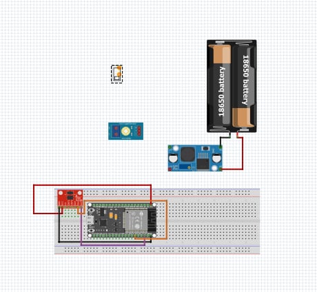
BUCK Grnd to ESP32 G, BUCK + to ESP32 VIN be careful to NOT reverse those else the magic smoke be released. Put the switch in the + line between the battery and VIN.
Don't understand what that red board is on the bread board nor the green board top center.
Why did you pick 47K and 10K for the voltage divider, what do you expect to do with that?
The red module is an accelerometer, I think the connection is alright since I've verified it online. While the green module top center is a voltage sensor, coZ I want to monitor battery health. I'm confused where to connect it to the batt. Also, nvm on the resistor I don't think I need a voltage divider. I initially wanted to add resistors for safety measures. Thank you for ur insights
Ok, or just look at the markings on the accelerometer module.
If you want to monitor battery health, you have two choices, the red or positive terminal, or the black or ground. That is as basic as it gets, think!
Search google with the following arduino measure battery voltage. Lots of info re measuring battery.
Given wanted to add resistors for safety I think a course in basic electronics is in order.
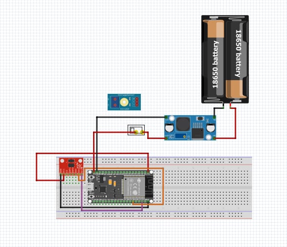
The power path looks ok as long as the buck input and output are correct, I can't see it well enough to be sure. I have no comment re the red board as I can't see the pins. This is why we say a photo of a hand drawn is fine.
Okay, thank you so muh
Just know that the buck regulator draws current when it is hooked to your batteries. Measure that when the power switch as positioned is open and see how much. Decide if that is acceptable.
You can place a (or the) switch in series with the battery V+ line before the regulator to reduce the current to zero.
Another module you might like is this one
which passes very low current when off. They have versions that handle higher currents.
I use 2S Lipo batteries and switch them on with that module; the buck regulation is downstream to that.
You can measure the battery voltage with the Arduous Arduino board and use the module's ability to turn off on command if the voltage is too low.
a7