voltage divider gives me not what i expect with buck converter in line

I am making a simple voltage divider that should output 3.2V (or close to) and it does, until I attach the wire to a pin on the teensy 3.2 at which point i get 1.6V. What am i doing wrong?

Here is the info on what I am doing...

I was trying to do a "write to EEPROM on power loss detect" sorta thing that i found here...

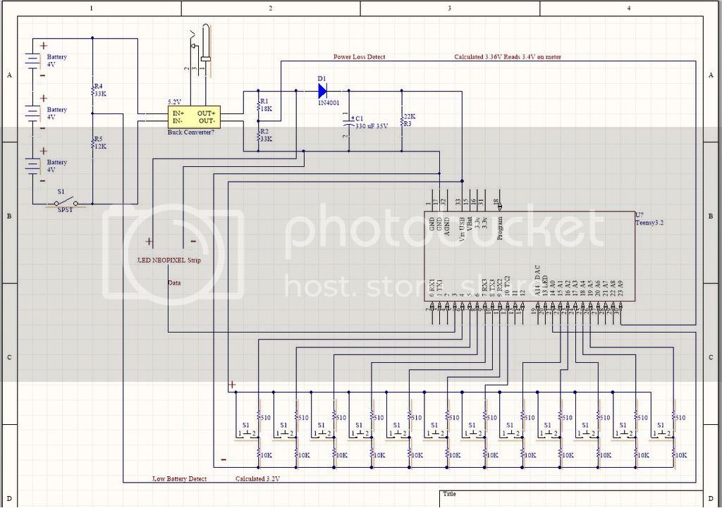
this is my first schematic...

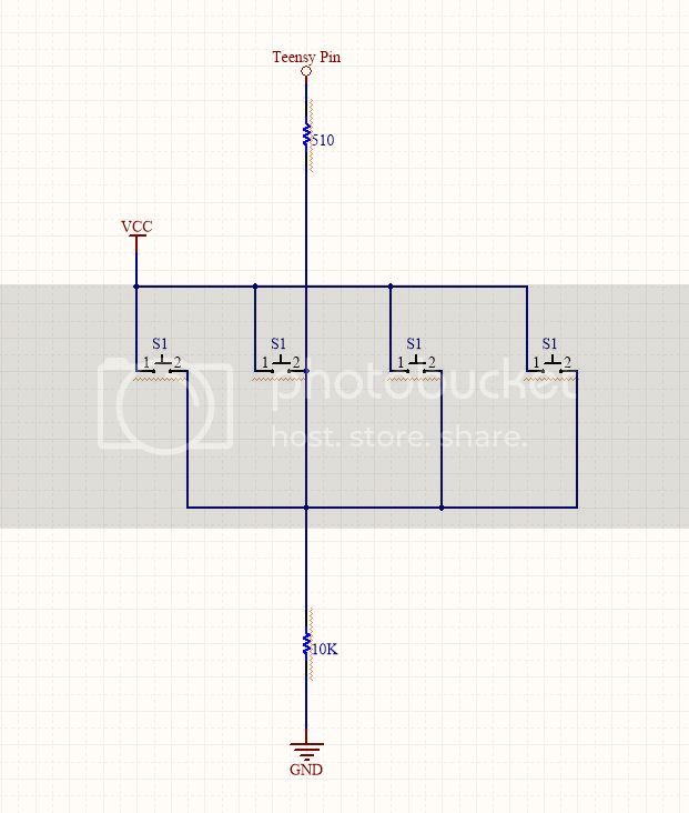
it should also be noted i have a bunch of push buttons wired to a bunch of the pins each with a 10K resistor to ground and ~500ohm to pin input but i didnt draw it in the diagram. The power in to each of the buttons and the 10K to ground are Vin and Ground directly before the teensy... so meaning after ALL the other electronics (eg caps, diodes, resistors, buck converter etc)

the battery was purchased a long time ago, i do not have any purchase history for it so I cannot say for sure what it is, but it is a rechargeable 5V (i actually get 5.2V out of it) li-ion battery probably from AliExpress kinda like this one...

aliexpress battery

i may not have the right power input on the teensy3.2 component in the diagram... in real life I have it wired to the 5V pin (not using the USB connector) maybe its the same pin on the diagram.. i wasnt sure. in the diagram i put it to Vbat... maybe i should have just put it to Vin USB...

This WORKS to detect power failure... (eg when i flip the spst switch off). I write to 56 bytes (only if they differ that what is there) and it works flawless, every time.

however I then tried to detect just low battery (to make the LEDs flash when it was getting low so you knew u needed to recharge soon) and i found that the battery never drops below 5.2V... which was weird.

So I pulled open the battery and found that it is actually 3 - 4V cells in series to make 12V with what i think is a buck converter to 5.2 (which would explain why it never dropped below 5.2).

Here is the buck converter...

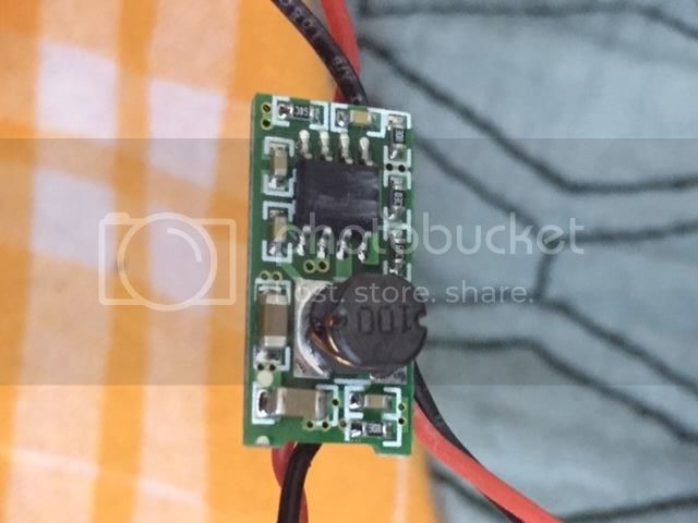
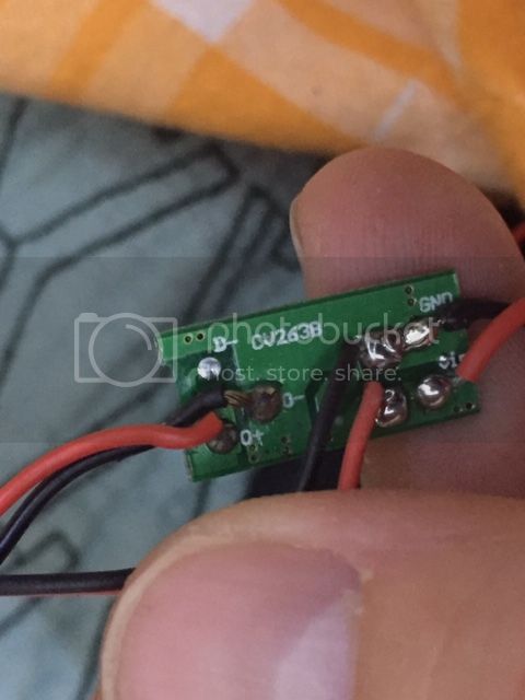
(i couldnt find this guy online)

So I then made my voltage divider for low battery detection before the buck converter like in this schematic..

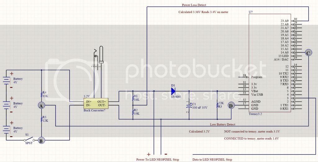
and if i read voltage at points A and B when the wire is NOT connected to teensy's pin A0(pin 14) I read 3.1V (which is what i want) but when i connect the wire to pin A0 it reads 1.6V between points A and B and also between points C and D (i cannot read between C and D when the wire is not connected obviously).

Why would this be? are the ground lines before and after the buck converter not connected? should I connect them? Or how would i make that read close to 3.3V when the wire is connected to the teensy?

Any help is appreciated.
Thanks

You should be connecting to power to Vin not Vbat. You ony have 0.75V less than is coming out of the converter due to the diode. So turn up the output until you get about 5V on the Vin as this goes through a regulator.

From the looks of it the ground of the converter is the same on both sides but measure it with a meter to be sure.

Are the LEDs removed so as not to load the battery during this test?

i apologize, i didnt explain that well. I do have power connected to Vin on the teensy in real life. I wasnt sure (as far as the diagram goes) which pin that was on the component in the diagram. (it's my first time using a schematic program).

I do have 0.75V less going to the teensy because of the diode so I am getting 4.5V on teensy (i knew that, forgot to mention it.) I am ok with that. (I dont think i can turn up the output on the buck converter, or at least, i dont know how.)

the LEDs are not removed, however i can press one of the buttons to turn them off... and i did and got the same readings (on both detection lines) with LEDs full brightness compared to off... however... when i was reading it just now, i noticed a solder splat connecting pins A0 and A1! DOH! so i guess it was splitting the voltage between the pins?

Problem solved! I removed the solder splat and i am getting a reading of 3V (the battery is used up a bit now so not 3.1) on pin A0 with leds on full brightness or off.

Thanks a ton!

I do have 0.75V less going to the teensy because of the diode so I am getting 4.5V on teensy (i knew that, forgot to mention it.) I am ok with that.

You might be OK with it but is the Teensy? The regulator on it might be a low dropout regulator but can it deliver 3V3 from just a 4V3 input? I would check the data sheet of the regulator.

Schematics are supposed to show real life, they are practically useless when they do not.

i noticed a solder splat connecting pins A0 and A1! DOH! so i guess it was splitting the voltage between the pins?

Well that in itself would not make any difference because the input impedance of the analogue inputs is way too high to show any loading effects.
Your splat must have been making a connection to somewhere else as well.

mohawkpiper:
I am making a simple voltage divider that should output 3.2V (or close to) and it does, until I attach the wire to a pin on the teensy 3.2 at which point i get 1.6V. What am i doing wrong?

It should also be noted i have a bunch of push buttons wired to a bunch of the pins each with a 10K resistor to ground.

10K resistor to ground? .... if 10k goes to ground, then this 10K will then be in parallel with your 33k of the divider, which then effectively makes your divider have 18k on the top branch and 8k on the bottom branch. So (8/26)*5.2 V = 1.6 volt.

Maybe you can put a 36k on the lower branch of your existing divider. And instead of having the 10k resistor for the push-buttons.... make that push-button resistor a 36k one.

And the resistor for the upper branch of the divider could become a 10k one (instead of the existing 18k).

So I am getting all the right voltages at all the right places.... 5.2V after buck converter, 4.5V after diode on teensy Vin and Grnd, 3.4V one voltage divider (might remove this one, as i dont really need it with the new one added) and 3.2 (on a full battery) on the other voltage divider, and the whole thing is running as I expect...

however I am still learning all this so let's continue for educational sake.

Grumpy_Mike:
You might be OK with it but is the Teensy?

online it says the teensy can operate at 3.7-6V, 4.5V is in that range, so yea, i think the teensy is ok with it right?

Grumpy_Mike:
The regulator on it might be a low dropout regulator but can it deliver 3V3 from just a 4V3 input? I would check the data sheet of the regulator.

by regulator do you mean the thing that i pulled out of the battery and believe to be a buck converter? or do you mean the 1n4001 diode?
if you mean the assumed buck converter, i have no way of knowing what that is, or where it came from. I bought the battery ages ago and have no purchase history... and the buck converter was inside the battery wrapping, and i couldnt find any info on the number that is printed on the board.

and I don't understand why I would need to deliver 3.3V from a 4.3V input? I don't understand that question.

Grumpy_Mike:
Schematics are supposed to show real life, they are practically useless when they do not.

i used ciruitMaker, and there was no Vin on the teensy I grabbed from the library... so do I use VUSB? I am not using the usb jack, I am soldered directly to the Vin and Ground pin.

@Southpark - I have 14 buttons... each with a resistor. It was my understanding these weren't dividing any voltage but rather giving a weak connection to ground driving them LOW unless they were pressed then they went 4.5V (because that is the input power) driving them HIGH as per this tutorial.

I will update the schematic in a day or two to show everything as it actually is so that it is true to the real thing.

also... i am driving 54 leds as i left out how many previously.

ok well i don't really have enough room to do the entire schematic... i am missing two buttons..

and each button (except two of them) are actually four buttons wired together like this...

end product (pulled open currently)...

video of end product (video was before adding power detection failure, low battery detection, and writing to EEPROM)

LED rubik's cube