I want to make generic continuity cable tester on my arduino, which means it can test x amount of conductors in a cable.
I wonder if this is even possible because if I am not mistaken, the maximum amount of conductors in a cable that you can do continuity test on is equal to the total amount of GPIO pins on the board divided by two because one half will be sending the signal and the other half will be receiving the signal.
So the arduino uno has 14 I/O and 6 analog, if I use all of the pins, then the maximum pins I can test is a cable with 10 conductors, am I correct on this?
If I am correct on the above statement, that is the continuity test is limited by the amount of pins on the MCU, is there anything I can do on the breadboard side or some smart trick I can do on the coding side?
I've been researching this on the forum and came across this term "shift register" in this post (#4): https://forum.arduino.cc/index.php?topic=186461.0
It looks promising but I don' really know what it is or how it works,
Here is the sketch I came up with, it tests a single wire continuity, a_1 will be sending the signal and b_1 will be receiving the signal
Can you tell us if the ends of the cable have connectors installed or is this just bare wire? What type of cable, ribbon, twisted pair, color coded wires, etc?
Are you testing for broken wires or for improperly installed connectors? Makes a difference.
If the cable has connectors on each end, are you wanting to wire up mating connectors in order to make contact with the cable?
I have a 12 pin female cable that goes into a 16 position connector, these wires are terminated and must go into a specific position of the connector, that is what I am trying to test. If a wire is in a wrong position in the connector, then I would need a failure condition to show, so yes I need to test improper placement in a connector
Also, yes, I have a male counterpart for the female cable,
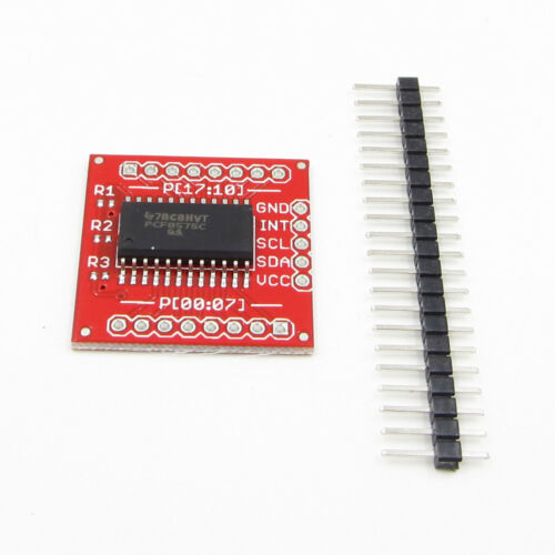
Suggest you use a couple of these "port expanders":
Each has 16 I/O pins and up to eight of these boards will parallel to the two I2C pins (A4 and A5) on the Nano (better than the UNO for actual applications) while you can also connect your display to indicate the success of a test.
The test process is to set one at a time of the I/O pins LOW and check that only the correct one on the other end of the cable reads LOW.
These port expanders can only pull LOW, so there is no conflict if a short circuit is present. (You can of course do the same on the Arduino by setting one pin to OUTPUT and LOW while the others are set to INPUT_PULLUP but it is inherent in the way the port expanders operate.)