My intention is to drive the coils from a car's 12V supply. (I know -- It's noisy and it's more than 12V.)
BUT... In some cases, even though the relays are designed to "latch" when they get just a pulse, their coils would have constant voltage for several hours.
Will continuous voltage cause a problem for this kind of relay?
If you follow the datasheet recommendations for coil voltage, you should be OK. There are no warnings against continuously powering the coils,except that it won't switch if you do so.
It is simple enough to design the control circuit to deliver the appropriate pulses.
The "control circuit" is the car itself... When the doors open, the relay triggers which provides power to an Uno. (Through a DC-DC converter.) It needs to latch to stay on when the doors close, but the Uno needs to be able to turn itself off via the other coil.
I kinda misspoke... sorry. I will also use the non-latching type from the same datasheet with the "Accessory" wire from the car, so Arduino knows when the key is turned. (Again, through the clean power supply.) This is the one that will have constant voltage.
This does lead to a follow-up question though:
If the Uno (through a transistor) energizes the coil to cut off its own power supply, is it likely that it wouldn't have enough time to toggle before the coil is de-energized?
Most latching relays aren't designed for continuous voltage to the coil. However, this relay is quite efficient (140mW, coil current 11.7mA). Still, I wouldn't attempt it myself unless confirmed OK by a KEMET technical rep. Even if acceptable, continuous voltage would probably degrade the coil's life expectancy.
Note that a standard non-latching DPDT relay can be wired (configured) to latch. Continuous coil voltage is no issue here.
I want the Uno to turn on (receive 9V power through my DC-DC converter) upon any car door opening, but I don't want it to lose power when the door closes.
Then, the goal is for the Uno to turn off its own power.
Is the door switch normally-closed? That is, do the contacts of the door switch become closed when the door opens and become open when the door is closed?
Is it OK if the door needs to be closed before the Uno can turn off its own power?
The door CIRCUIT is normally open when the door DOOR is closed. (Circuit closes when the door opens.)
Yes -- If the door is still open (which Uno needs to know) then it actually wouldn't be programmed to cut its own power. (Although a timeout might be a good idea.)
You need to unxerstand what "latching relay circuit" means.
It means that , for example , you press a N.O. push button, at the moment that button engages, iit suppies power to the coil of a relay. That relay has N.O. contacts that complete the circuit to power the coil through a different path that includes a N.C. push button , that when pushed, breaks the circuit powering the coil , which , if you remember, was originally engaged when the other button, ( the N.O. button). So since you pushed tgat button , engaging the relay N O. contacts that then provded a secondary path to power the coil, the relay is now "Latched". If you now press the N.C. button in series with those N.O contacts, and "break" the coil circuit , the relay denergizes , losing latch. The first butyon you pressed ( the one that engaged gge relay) , was the ON button. The second button uou pressed ( the one that Denergized the relay) was the OFF button. That is one example of a latching relay, but actually is a latching 3-phase contacor circuig. Imagine now, relacing both push buttons eith other relays driven by uC I/O.
Using just 2 SPDT relays with 12V coil, the first relay latches on when the door opens and remains on when the door closes. The second relay (controlled by the Arduino) is used to kill the power, but only if the door is closed.
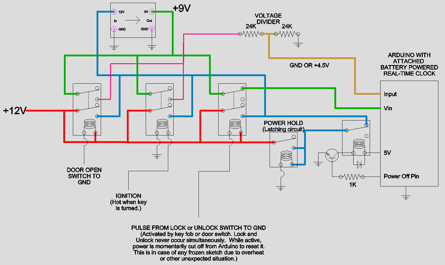
Thank you. After some thought, a diagram of my circuit is here. (At least the portion that handles powering the Arduino according to the state of doors and locks.)
None of the 5 relays is latching, although one of the relays (labeled "Power Hold") is used to latch the power supply. Three relays must be DPDT (12v), one can be SPDT (12v) (or wired as such), and the last one can also be SPDT (5v).
For simplicity, my original post didn't mention:
The Arduino would be powered up upon any of three conditions: A door is locked/unlocked, A door opens, or the key is turned.
The Arduino has a real-time clock, so even if it loses power and comes back on, it knows how long ago any of the above conditions were last met.
The whole purpose is to control video and audio recording onboard a fleet of vehicles, which I own for a my driving school business. It will record for a set time after the car is left unattended, and in addition to the circuitry shown, there is a pushbutton and display on the dash which allows the driver to disable video recording for a specified time period.... (Therefore there will be a 6th relay and related transistor, not shown, which affects 12V power to the mobile DVR.) This is for driving instructors, my employees, who normally need to be recorded. But since students can legally deny consent to be recorded, they need to be able to disable it for the length of one lesson, no more than twice per day. It must default to record, but if disabled it should resume recording after a timeout.
In an earlier implementation, the system froze occasionally in real life use. (Either the display or the Arduino.) I don't know why. (Heat, memory management, etc.) I can't know for sure it won't happen again, and therefore, this implementation resets the Arduino by momentarily removing power while the key fob "lock" or "unlock" buttons are pressed. This doesn't disrupt anything because upon startup, the Arduino remembers what it was last doing, and checks it realtime clock against the time that it was supposed to resume or stop recording.
My original question remains, although slightly different: Although I won't use a latching type relay, are the relays shown in the spec sheet of my original post appropriate? (The spec sheet includes 5V and 12V relays, DPDT, and not all of them latch.) EDIT, Minor correction: There's no reason they can't all be 12V DPDT relays, even if I don't use the second switch. So consider my diagram modified to use 12V for the rightmost relay. My concern is what jremmington said above: "The car cannot safely provide the voltage required for the relay, so you will need extra circuitry." Respectfully, that doesn't sound correct to me. I know the car voltage is noisy and unstable, but to my knowledge a relay coil isn't sensitive like a mircocontroller, and the Arduino itself is getting clean, regulated 9V power.