That's a terrible data sheet! It doesn't even make it clear how the output indicates the measured distance. You seem to be working on the assumption that the output is an analog voltage that varies with the distance. But it could also be that the output is digital and the pulse length indicates the distance. Are you sure you are reading the sensor correctly?
ecce_lex:
Why is the output from the sensor more stable when I use a 8k ohm resistor for connecting it to the Arduino?
Do you have the 12K pull-up resistor on the device's output, as indicated in the data sheet?
ecce_lex:
2. Why is the green LED significantly dimmer than the red LED? How could I make it the same intensity?
Its just a dimmer led, I suspect. Or your Arduino output is damaged or the led is damaged. What if you use another pin? If that makes no difference, dry dropping the series resistor to 330R or 220R
I did use a pull-up resistor 12.5k ohm on the sensor's output. It was about 8k ohm initially but replaced it with a 12.5 k ohm resistor.
Here is a better version of the data sheet: http://www.sharpsma.com/webfm_send/1206
This sensor does not measure distance, it's a proximity sensor (gets triggered at 15cm or closer) - the output is not proportional to distance.
I have tried another pin on the Arduino and the luminosity of the LED stays the same. I have removed the resistor altogether and there is a (slight) increase in brightness. This really puzzles me.
By adding the resistor, you are reducing resolution of the sensor so the intervals in your readings are greater and I believe will be at a different scale than you see without the resistor. Adding the resistor isn't necessary.
There are 3 factors when it comes to LED's that affect whether one LED is apparently brighter than another. One is the intensity, which can be found on the LED datasheet. Another factor is the beam angle, also located on the datasheet. If one LED has a wider beam angle then it will be more diffused and appear less intense. lastly, time. Greens tend to degrade quicker than reds. So if you've applied power to these for >200 hours, the green will be dimmer given both LED's have the same intensity rating and the same beam angle.
You'll find a lot of information on the datasheets.
The issue with the LED seems to be independent of the build quality of that particular LED. I have switched the green and red LEDs between them - now the red LED is significantly dimmer. I have also tries several Arduino pins - same result.
Why then does the data sheet say a resistor should be added?
ecce_lex:
I did use a pull-up resistor 12.5k ohm on the sensor's output. It was about 8k ohm initially but replaced it with a 12.5 k ohm resistor.
Your schematic shows no pull-up resistor. It shows a resistor in series with the sensor's output. A pull-up resistor connects a pin to Vcc.
ecce_lex:
Here is a better version of the data sheet: http://www.sharpsma.com/webfm_send/1206
This sensor does not measure distance, it's a proximity sensor (gets triggered at 15cm or closer) - the output is not proportional to distance.
Not noticeably better in my opinion! It says:
The GP2D150A is a distance measuring sensor with digital output.
But it doesn't say how the digital output indicates the distance.
So, you are saying the output is digital and indicates the presence/absence of an object, not the duistance to it. Then why are you connecting it to an analog pin, taking multiple readings with analogRead() and averaging them? That is what you would do with an analog signal. You can simply connect it to a digital pin (Arduino analog pins can also act as digital pins) and take a single reading with digitalRead().
ecce_lex:
I have tried another pin on the Arduino and the luminosity of the LED stays the same. I have removed the resistor altogether and there is a (slight) increase in brightness.
Never connect an LED without a series resistor, you could damage the Arduino output. The technical term to describe your green led is "knackered".
Pull-up resistor: thank you for clarifying. No, I had not used one. When I do use such a resistor, the red LED is always on. I believe it may have to do something with the "threshold" value. Shall check.
LEDs: I have two LEDs: a green one and a red one. My issue is that one of them - the one which is on when nothing is detected - is significantly dimmer than the LED which turns on when sensor is triggered.
What I meant was that I tried switching the LEDs: I put the red one where the green one was, and viceversa. Now the red one was dimmer - I conclude it's not the LED, but the circuit that makes one dimmer than the other. Does this make more sense?
ecce_lex:
When I do use such a resistor, the red LED is always on. I believe it may have to do something with the "threshold" value. Shall check.
Your sketch prints the averaged value it is reading to the Serial monitor. What values do you see there when there is/isn't an object in front of the sensor?
ecce_lex:
LEDs: I have two LEDs: a green one and a red one. My issue is that one of them - the one which is on when nothing is detected - is significantly dimmer than the LED which turns on when sensor is triggered.
What I meant was that I tried switching the LEDs: I put the red one where the green one was, and viceversa. Now the red one was dimmer - I conclude it's not the LED, but the circuit that makes one dimmer than the other. Does this make more sense?
Sounds like you may have a damaged Arduino output. Try changing to a different pin for the dimmer led.
PaulRB:
Sounds like you may have a damaged Arduino output. Try changing to a different pin for the dimmer led.
I did try that - it's still dim.
PaulRB:
Your sketch prints the averaged value it is reading to the Serial monitor. What values do you see there when there is/isn't an object in front of the sensor?
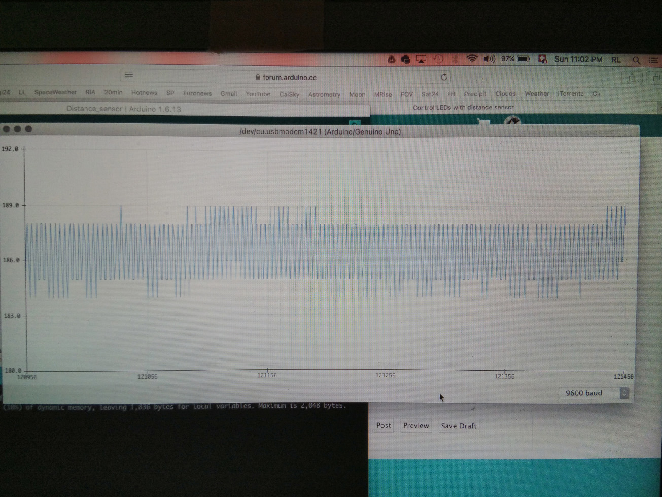
The average value when not detecting is about 42. The average value when triggered varies, and is between 150 and 250, depending on the object and distance to sensor.
I have attached images of the serial plotter for each case.
That value of 42 will be read as LOW by digitalRead(), but 250 is not high enough to read as HIGH. It should be 900+. Do you still have a resistor in series with the output?
This led thing is confusing. You have tried other pins and swapping over the leds. So you know that both red and green leds are both capable of shining brightly. What about the led series resistors? Have you tried swapping them? Use a multimeter to chef their resistance is as expected. Also use multimeter to check the voltage drop across the led and across the series resistor when the led glows dimly. Also check your connecting wires with the multimeter.
Distance measurement range: 10 to 80 cm (3.9 to 31.5 inches)
Analog output voltage corresponding to distance
Operates on 5 V supply
3-pin JST connector
Two mounting holes spaced 1.46 inches (37 mm) apart
Looks exactly like what you have except it gives you a 0-5V coorisponding to distance.
Thank you for your replies. Follow below three photos of the setup. Don't laugh at my sticking the microcontroller behind the breadboard - I don't have a lot of space
Wire-up (sorry it's links - photos will not show for some reason)
Shall follow a post with the suggested measurements.
JimLee : you are correct, that model seems more apropriate for actual use. This one seems to have a 3-15cm range but sensor output and distance to object do not seem to be connected in any recogniseable way. Readings are quite erratic and actually touching the laptop shifts the average value up a notch of you can believe it.
I have replaced the 12K ohm pull-up resistor for the sensor with a 460 ohm resistor. The output has changed: it reads zero when not detecting and about 100 when triggered.
The voltage across the dim LED is 10mV. The voltage across the bright LED is 1.88V. Both resistors are 460 ohm.
I have tried switching to another position on the breadboard - in case it may be damaged somehow - but still the same result.
Hi,
Have you tried both LEDs being Green and see if its a position problem.
Can you just connect a RED LED and 460R from 5V to gnd and measure the voltage across the LED.
Then do the same with the GREEN LED.
That is 5V not an output pin.
Lets do some basic LED tests.
Tom.....
PS Your 460R, NO! ! ! Yellow, Purple, Brown, == 470R
PSS. Why have you got the 10K? ? ? resistor in series with the 5V supply to the sensor?
The 10K, is it really 10K ? ? ?
Use your DMM and check ALL your resistors in the circuit.
ecce_lex:
I have replaced the 12K ohm pull-up resistor for the sensor with a 460 ohm resistor. The output has changed: it reads zero when not detecting and about 100 when triggered.
460R is a very strong pull-up resistor. I would have expected that to give a higher reading, for both detecting and not detecting, compared to 12K. But you are getting lower readings. You have correctly connected the 460R as a pull-up, not as a series resistor?
ecce_lex:
The voltage across the dim LED is 10mV. The voltage across the bright LED is 1.88V. Both resistors are 460 ohm.
What is the voltage drop across each of the 460R ?
At the moment, my reaction to your observations for both the sensor output and the leds is "that can't happen"!