Control multiple leds by an analog reading after going trhough an amplifier

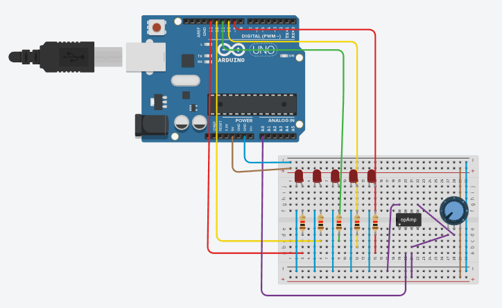
Greetings, this my first post and I hope you could help me. I have found myself in a problem while doing a little project. My task is to do a home-made glucometer, but dont let it deceive you, it's just based on the voltage received hence to the amplifier. I´ve been working with a code and got all of the components I thought I would need. I´m quite new at this so I think that there might be a problem in the coding. The idea is that using the Voltage from the blood that goes trough the amp and to an analogic input of the Arduino, then using 'if' conditions turn Leds on or off depending of the value.
Right now the problem is that just one Led is turning on, and no matter what I do it does not change.
Here's the code:

int ledUH= 13;
int ledH= 12;
int ledN= 11;
int ledL= 10;
int ledUL= 9;
int INA= A0;
int ledState = LOW;
void setup() {
  // put your setup code here, to run once:
pinMode (ledUH, OUTPUT);
pinMode (ledH, OUTPUT);
pinMode (ledN, OUTPUT);
pinMode (ledL, OUTPUT);
pinMode (ledUL, OUTPUT);
pinMode (INA, INPUT);
Serial.begin(9600);
}

void loop() {
  // put your main code here, to run repeatedly:

int x = analogRead (INA);
int xDoubled = x*2;

Serial.print(INA);
Serial.println("  sensando");
Serial.print(xDoubled);
Serial.println("  Doble");

if(xDoubled <=170){ //Very low glucose
  digitalWrite (ledUL, HIGH);
  digitalWrite (ledUL, LOW);
  delay(5000);
}
if(300>xDoubled <500){//Low glucose
  digitalWrite (ledL, HIGH);
  digitalWrite (ledL, LOW);
  delay(5000);
}
if(510>xDoubled <690){//normal glucose
  digitalWrite (ledN, HIGH);
  digitalWrite (ledN, LOW);
  delay(5000);
}
if(750>xDoubled <860){//Pre-diabetis
  digitalWrite (ledH, HIGH);
  digitalWrite (ledH, LOW);
  delay(5000);
}
if(xDoubled >=900){ //Very high Glucose Level 
  digitalWrite (ledUH, HIGH);
  digitalWrite (ledUH, LOW);
  delay(5000);
}

}

I have never written if statements like that , so it maybe illegal syntax ( I stand to be corrected )
Try along the lines of using either the AND or OR conditions along the lines of this example

if ( (x >=600 ) && (z <=96))        

Good job with code tags on your first posting.

Your syntax for the conditional test of a value within a range is not correct.

//if(300>xDoubled <500){//Low glucose
if(xDoubled > 300 and xDoubled < 500)

Please provide a sketch of how your leds are wired.
Your blink code does not look correct as you are just turning them on/off with no time in between.

digitalWrite (ledUL, HIGH);
digitalWrite (ledUL, LOW);

Thank you Cattledog, I modified the time and now it´s blinking, but still just the LedUH is turning on, the problem with this is that it should not be that one, because in this momente there is no blood so it should be reading the minimun voltage, so the one that should be turning on is the LedUL


This is the sketch of the circuit. The pins 3 an 2 of the amplifier are the ones that connect to the receiver of blood.

Thank you for the reply, I will try it

What do your serial prints statements say

int x = analogRead (INA);
int xDoubled = x*2;

Serial.print(INA);
Serial.println("  sensando");
Serial.print(xDoubled);
Serial.println("  Doble");

Ok, before answering the questions about the serial print I made some changes to the code, first I made the ones that you and @hammy said, then I changed the int of xDoubled for a float, also did that with the int for "x".

Now the LedUH is always on, but the LedN, is blinking, which leads me to the serial prints. (Still wrong that it blinks because there is no blood, but it's progress I guess. I think it has to do with the parameters of the 'if')

I realized I made a huge mistake, in the Serial print I was not printing the Analog read, that's why it didn't changed. Now with this change made the Serial monitor show something diferent

Captura de pantalla 2022-12-11 160516

I tried changing the multiplier of xDoubled and depending of what multiplier I use does change but for some reason if I multiply it by 1 the serial print goes crazy and none of the Leds turn on(Except the UH which is always on for some reason).

int ledUH= 13;
int ledH= 12;
int ledN= 11;
int ledL= 10;
int ledUL= 9;
int INA= A0;
int ledState = LOW;
void setup() {
 // put your setup code here, to run once:
pinMode (ledUH, OUTPUT);
pinMode (ledH, OUTPUT);
pinMode (ledN, OUTPUT);
pinMode (ledL, OUTPUT);
pinMode (ledUL, OUTPUT);
pinMode (INA, INPUT);
Serial.begin(9600);
}

void loop() {
 // put your main code here, to run repeatedly:

float x = analogRead (INA);
float xDoubled = x*2;

Serial.print(INA);
Serial.println("  sensando");
Serial.print(xDoubled);
Serial.println("  Doble");

if(xDoubled<=170){ //Very low glucose
 Serial.println("Very low");
 digitalWrite (ledUL, HIGH);
 delay(5000);
 digitalWrite (ledUL, LOW);
 delay(5000);
 
}
if(300<xDoubled and xDoubled <500){//Low glucose
 Serial.println("Low");
 digitalWrite (ledL, HIGH);
 delay(5000);
 digitalWrite (ledL, LOW);
 delay(5000);
 
}
if(510<xDoubled and xDoubled <690){//normal glucose
 Serial.println("Normal");
 digitalWrite (ledN, HIGH);
 delay(5000);
 digitalWrite (ledN, LOW);
 delay(5000);
 
}
if(750<xDoubled and xDoubled <860){//Pre-diabetis
 Serial.println("High");
 digitalWrite (ledH, HIGH);
 delay(5000);
 digitalWrite (ledH, LOW);
 delay(5000);
 
}
if(xDoubled>=900){ //Very high Glucose Level 
 Serial.println("Very High");
 digitalWrite (ledUH, HIGH);
 delay(5000);
 digitalWrite (ledUH, LOW);
 delay(5000);
 
}

}

There are gaps in your coverage.

There are values that do not match any of your conditions. Like around 505 and 700.

You could use case ranges in a switch/case statement, it makes this kind of if/else sequence easier to read and check.

    switch (someValue) {
    case 0 ... 175 :

// code for 0 to 175

    break;

    case 176 ... 299 :


// code for 176 to 299
 
    break;

and so forth. The bonus is that the compiler won't let you overlap ranges... you still have to cover the ranges you are interested in, though.

a7

1 Like

The analog reading of 294 with no blood is a separate hardware problem.
The code is responding correctly to that value.

the LedUH is always on,

int ledUH= 13;

Because of the built in led on pin13, it can act differently from the other i/ pins. Try moving the LEDUH to pin 8.

I would also suggest that you write a simple test program to turn on and off each led to confirm that they are wired correctly.

Greetings @alto777 thanks for the reply, I will try doing this, but before that I have a question with the sintaxis
Would it be something like this

switch (xDoubled) {
    case 0 ... 170 :
  Serial.println("Very low");
  digitalWrite (ledUL, HIGH);
  delay(2000);
  digitalWrite (ledUL, LOW);
  delay(2000);

    break;

    case 176 ... 299 :
  Serial.println("Low");
  digitalWrite (ledL, HIGH);
  delay(2000);
  digitalWrite (ledL, LOW);
  delay(2000);

    break;
 }

Or am I wrong?

@cattledog You are completely right, the hardware was the issue with that false reading, I changed the amplifier and it started giving a lecture of 0 so now the correct Led (LedUL) is blinking.

And I will try changing the pin of the LedUH as you said.

Looks good.

You can add individual numbered cases like usual, and I sometimes put a

    default :
      Serial.print(xDoubeld);
      Serial.println(" not handled!");

      break;

case in my switches to call attention to a missed value if I don't want to. Miss any values.

Also… just me but flashing 2 secs on 2 secs off would not work… life too short. A glance might miss it. I am sure UI/UX experts would say how fast to flash for effective communication; I suggest about 5 to 10 times faster.

a7

Thanks, I'm gonna add that 'default', you never know when you're gonna have a strange reading hahaha.
You are right about the Leds' speed, but in the final version of this project I intend to do it with an Lcd_I2C to display the values and the Glucose level message.

Since delay() owns your flow, having 4 seconds in there makes development annoying, at least for me, so it isn't just a matter of UI/UX in the final device.

But I am impatient and have much less time left than I have been privileged to live so far…

Sometimes I

# define K2000 2000

and use K2000 all over the place, leaving one line of code to change to adjust all the flashing.

a7

except maybe for
https://forum.arduino.cc/t/activating-leds-with-analog-readings-from-an-amplifier/1064258/3
???

Other than First Post I have a few questions beginning with exactly what operational amplifier are you using and what is beside it? Looks like a pot. I am not seeing any means to control the gain of your op-amp unless I missed it. Exactly what is the output from your sensor? You may want to give this a read. A link to your sensor data sheet would help as well as again a link to your operational amplifier data sheet.

Ron

You're right, this is the first day using the forum, and for some reason I couldn't find the original post which until you answer it, and I was kind of desperate so I made this one, I'm sorry if it bothered you

@Ron_Blain thanks for your reply, I will read that link that you gave, and about the amplifier, I'm using a INA114, this is the link to the datasheet, and yes that beside the amp is a pot, my thought was using that pot to control the gain by connecting it to the pins 2 and 3, I don't know if I'm mistaken. And about the sensor, due to the complexity and numerous kinds of blood test strips I am using something more rudimentary. I'm using mini plates of copper connected to the pins I already mentioned by crocodile clips. If you like I can send an actual picture of how I set.

You are totally correct, shortly after your recomendation I changed the delay and it's better.

And about that K2000, I'm sorry I'm not familiarized with it, could you expand about it?

OK, I gathered that was what was going on. You have an Instrumentation Amplifier with programmable gain. That explains the Gain using the pot. While they typically want Rg to be a stable 1% precision resistor I would configure the pot like this:

I would use a 10 turn or motr 50k Pot. You can see how that would help, Friend of mine has one such machine, Given him by the VA (Veterans Administration . Not sure how your sensor scheme will play out

Ron

.