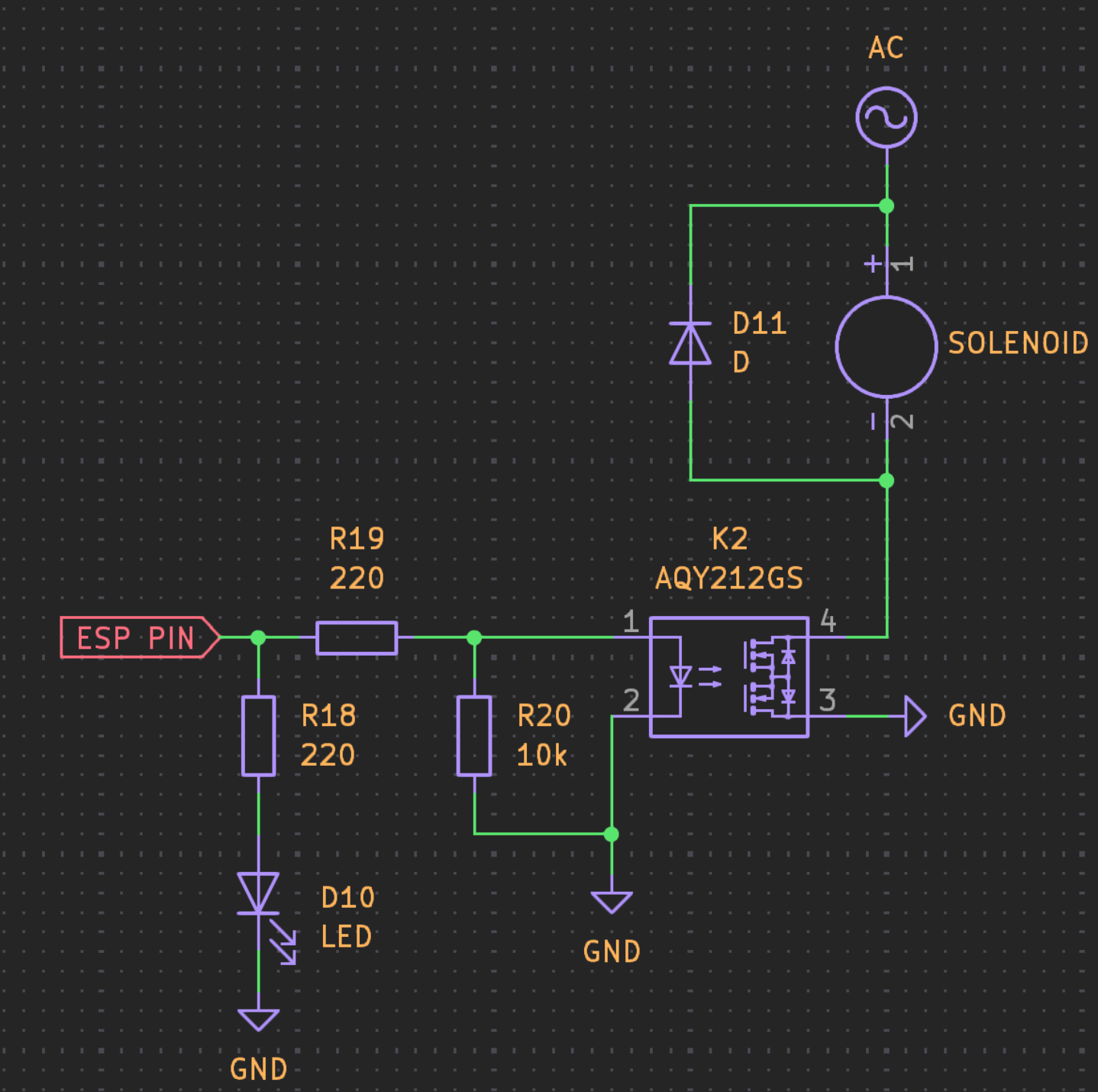
I need some help reviewing the schematic I have for controlling a solid state relay AQY212GS with a 24 volt ac solenoid hooked to it. I am controlling this relay with an esp32.
The LED in the relay has a forward voltage of 1.32V and a recommended forward current of 5ma to 30ma. R19 is 220 ohms for 9ma forward current.
Not sure if the 10k resistor is needed to ensure the solid state relay is off and if the indicator LED is implemented properly.
I don't do AC stuff normally, so I hope others can give you more valid advice. But I would say R20 isn't needed. And I don't think D11 works with AC. It would be fully conducting during the negative phase of the AC power. But I don't know what replaces it.
@ davemg is right, a diode won't work for AC, it will be a short circuit on the AC negative swing. I would use a bidirectional TVS diode with a standoff voltage of 32.
EDIT: OOPS! Make that 40V, 24VAC RMS = 34V peak.
If instead of using the SSR you use a TRIAC it will switch off when the current is zero, thus no voltage spike in the coil (it's demagnetised at that point).
Start with 47 or 100Ω and 100 nF.
General purpose solution, also often seen in combination with TRAICs (not for the inductive kick but to help them switch of when controlling inductive loads - though modern snubberless TRIACs don't even need that).