My modules are so similar to the the system showed here :
the only difference is ; number of modules and the voltage of motors
I have 5 modules in one Display ,13 Displays ..so i have 65 modules in total
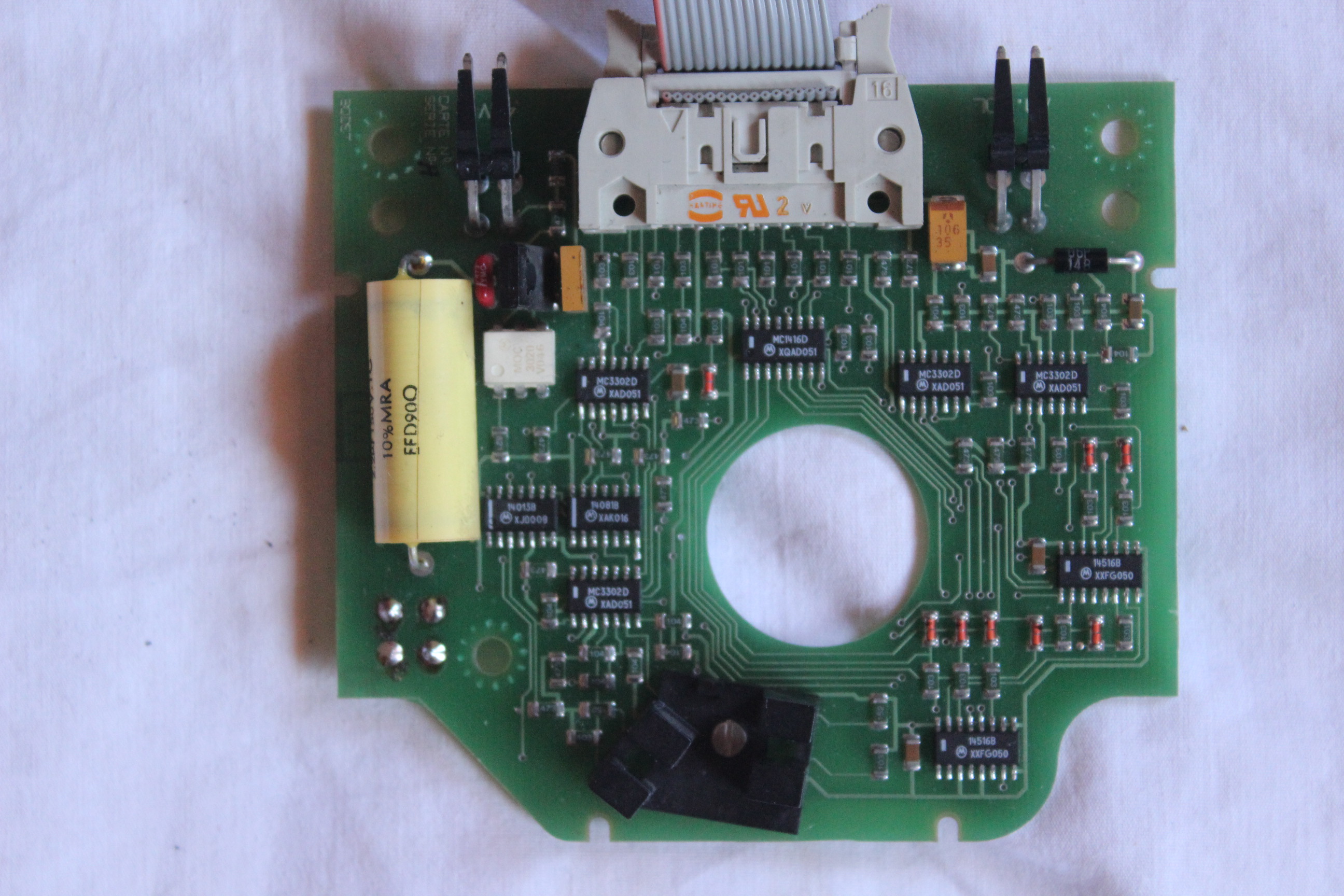
My split flop displays are from Bodet ( a French company ) with 48VAC synchronous motors and 12VDC for the circuit, a I have 16-pin output from the motor controller !
I contacted Bodet to get the schematics of the motor controler ... still waiting.
The motor looks like it might be a stepper motor. You might be able to run it with a suitable stepper driver.
The other question is position feedback. The odd-shaped black box on the circuit board looks like it would read slots in concentric cylindrical rings on the hub. What is the arrangement of slots?
Hi,
That motor is a 2phase synchronous motor, could be driven as a stepper, looks like it has a gearbox
As johnwasser has said it looks like a photo interrupter type control, you ca just see the interrupter on the control board.
If I remember when seeing them years ago, each time a digit had to change, they flipped though all the characters to find the sync position, then counted to get to the desired position.
Thanks soo much for the feedback, I saw 2 successful examples of desplay similar to my display .sending serial information from arduino to MAX232 RS232 driver IC in/out to the Sin/Sout lines of the display.
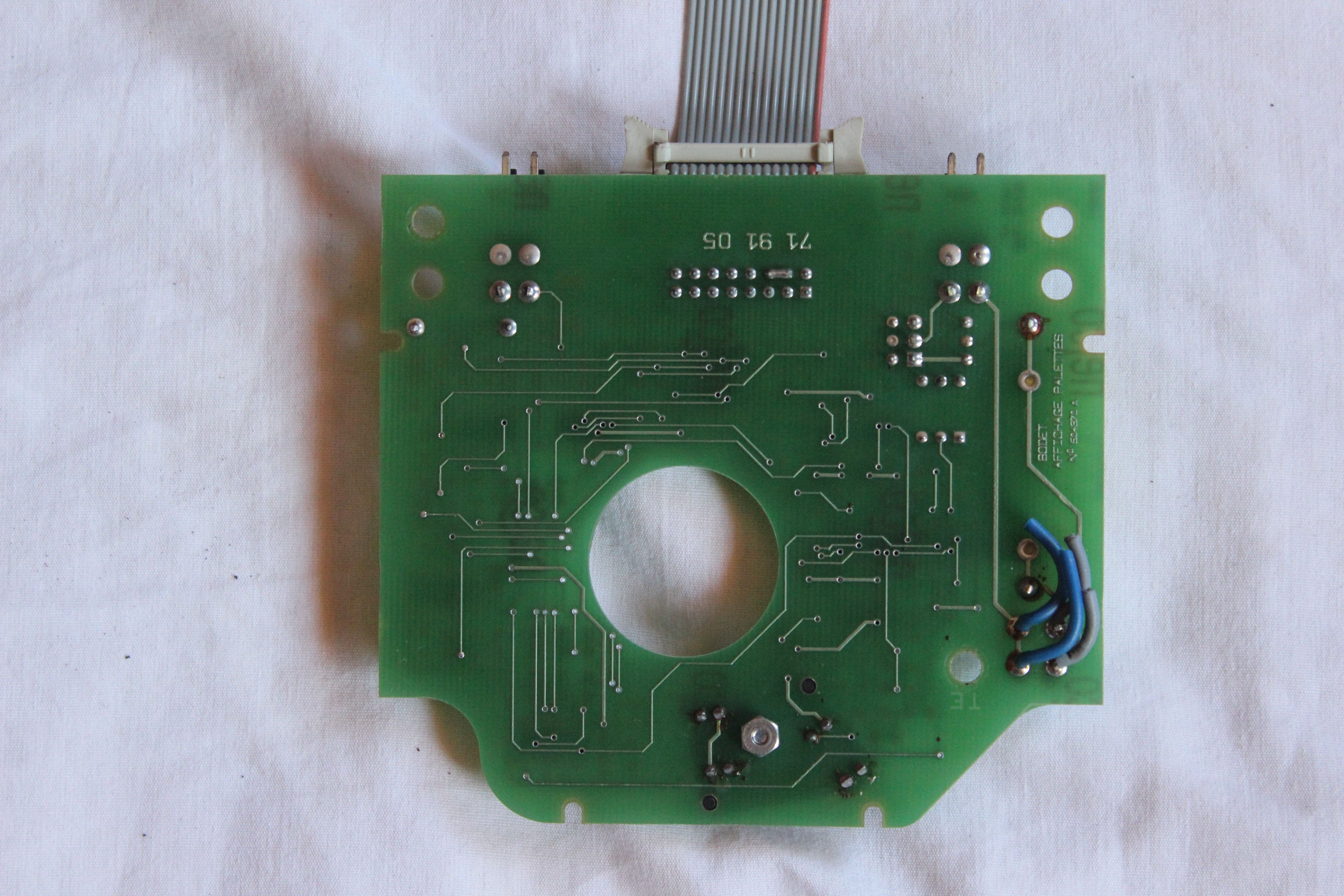
I attached 2 sharp images of both side of the motor driver .
johnwasser:
The motor looks like it might be a stepper motor. You might be able to run it with a suitable stepper driver.
The other question is position feedback. The odd-shaped black box on the circuit board looks like it would read slots in concentric cylindrical rings on the hub. What is the arrangement of slots?
johnwasser:
I tried to drive it with arduino motor shield the capacitor explode, it only support 12V
for the position feedback i confirm it's photo interrupter, by need to make some reverse engineering to use it !
Robin2:
I don't undertstand what you have and what you are trying to do?
Do you have a working display unit and are you just trying to figure out what commands it requires to present a specific character?
Or are you trying to replace the motor system with something completely different?
Or what?
Depending on your answer there will be follow-up questions
...R
Hello Robin2 ,
thanks for asking , I have 65 Split-Flap unit in a train station the units are connected with serial cable to a non functional old server, I want to replace the command System , and in order to make it I have a scenarios
i need to know how to control the motors and know the positions and connect them using I2C.
Someone just answered on youtube video he's controlling one unit : - YouTube
He said : Your controller board looks a lot newer than mine. Mine had older through-hole parts, and had parts spread over two boards. You should still be able to reverse-engineer yours easily enough. My circuit was just some LEDs to show the level of some of the outputs. Everything else was just connected directly to the Arduino.
a Youtuber made it work , he send me this comment :
I followed all of the traces on the board, and created a schematic using Eagle CAD. Most of the ICs were standard 4000-series logic gates, so I could easily look up the datasheets to see what each pin was for. From your photos looks like you've got some MC3302 comparators and a couple 4000 series ICs too. After I made the schematic I then used it to work out what I needed to do on the inputs for it to start/stop the motor, and to read out the sensors.
Moins
mehdidib:
I have 65 Split-Flap unit in a train station the units are connected with serial cable to a non functional old server, I want to replace the command System , and in order to make it I have a scenarios
i need to know how to control the motors and know the positions and connect them using I2C.
If it is only the server that has failed I don't understand why you need to control the motors. Can't you just send serial signals the same the server would have done. From you photos I suspect that all the motor control logic is in each unit.
You say you have 13 units with 5 characters in each. Do you know if each unit had 5 serial cables going to the server or only one serial cable?
If the serial system is standard RS232 you could probably control the system directly from a PC without any Arduino.
Or, assuming there is one RS232 serial connection for each unit, maybe you could use 4 Megas - one connected to the controlling PC and 3 display units and 4 display units on the other 3 Megas - communicate between the Megas using SPI or I2C. That would keep the Arduino programming to a minimum.
Robin2:
If it is only the server that has failed I don't understand why you need to control the motors. Can't you just send serial signals the same the server would have done. From you photos I suspect that all the motor control logic is in each unit.
You say you have 13 units with 5 characters in each. Do you know if each unit had 5 serial cables going to the server or only one serial cable?
If the serial system is standard RS232 you could probably control the system directly from a PC without any Arduino.
Or, assuming there is one RS232 serial connection for each unit, maybe you could use 4 Megas - one connected to the controlling PC and 3 display units and 4 display units on the other 3 Megas - communicate between the Megas using SPI or I2C. That would keep the Arduino programming to a minimum.
...R
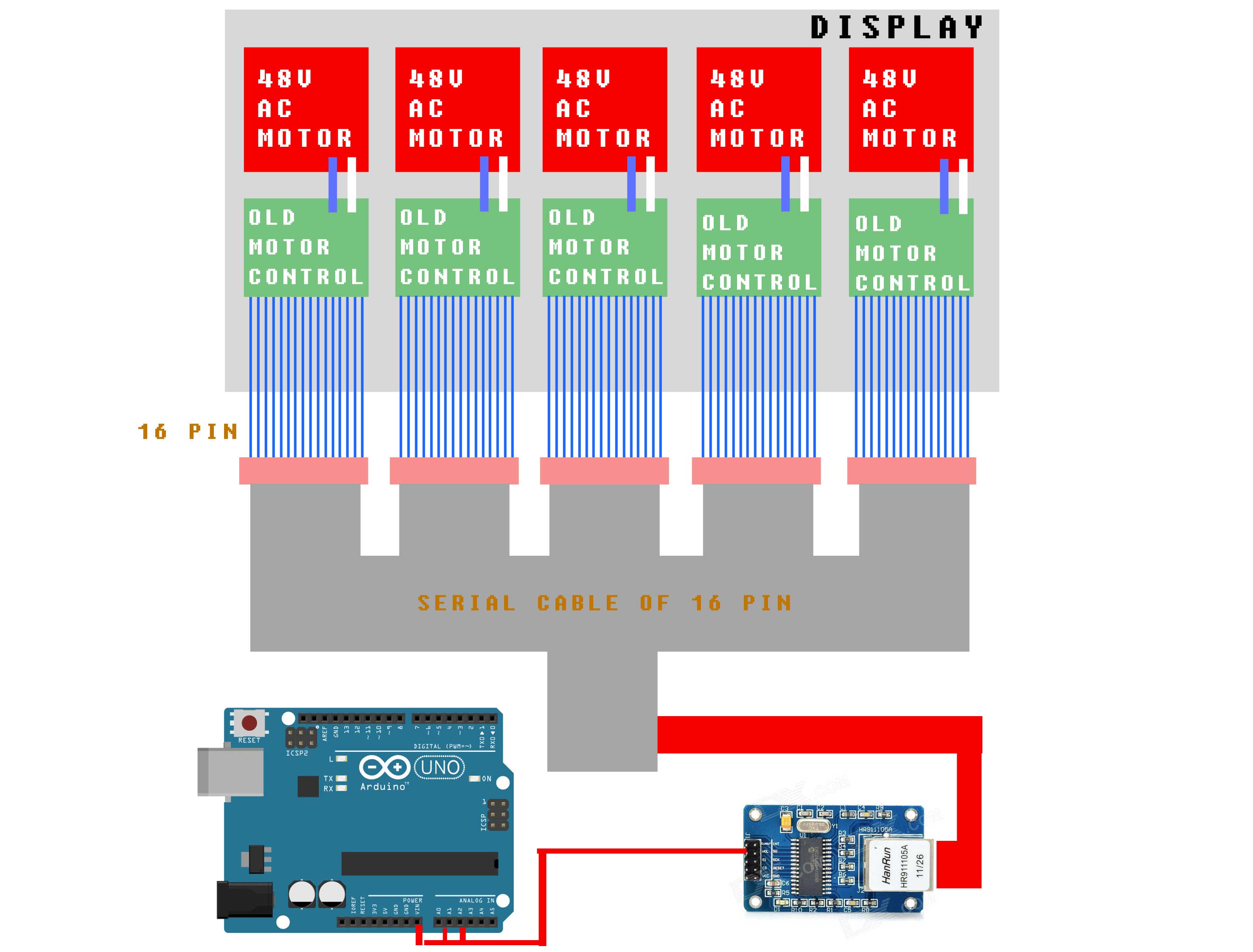
I attached an illustration to explain the system of one display i have 13 , i can't send the same serial signal because i didn't made my reverse engineering .
I can't make any sense of the image Sans-titre-1.jpg - what is it intended to convey? What is the thing that is connected to the Arduino?
In Reply #17 you lead me to think that there are only 2 serial cables and one sends data for 40 motors and the other sends data for 25 motors. Is that correct?
Rather than expect me to read lots of links and learn all about something I am never going to use perhaps you could provide a synopsis of each of the links. That way maybe I don't need to look at all of them.
Robin2:
I can't make any sense of the image Sans-titre-1.jpg - what is it intended to convey?
I'm beginning to think that the 5-conductor "serial" cable is a 16-conductor multi-drop ribbon cable. Perhaps the term "serial cable" means something other than what we typically use it for.
Robin2:
What is the thing that is connected to the Arduino?
It appears to be an Ethernet MAC which makes NO sense at all. I suspect it was used to represent a "12C to unknown interface adapter" of unknown design.
Robin2:
Rather than expect me to read lots of links and learn all about something I am never going to use perhaps you could provide a synopsis of each of the links. That way maybe I don't need to look at all of them.
The OP is trying to do reverse engineering while admitting to being "no good at reverse engineering".

