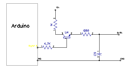
A few years back Grumpy Mike showed a circuit to control 0-10v with the following circuit.
But when I look at this circuit it appears that it would run opposite of the PWM. So if the PWM is set to 255 the output is 0v but if the PWM is set to 0 then the output is 12v. But I would prefer if the analog output ran the same as the PWM. So I was wondering if you could give me your opinion if this would work....
I suppose an inverter would work. I need both Analog 0-10v and PWM to be in synch because I am running 8 devices (4 analog and 4 PWM) and I only have 4 PWM lines after setting up the lcd.
But I am curious why the NPN won't work in the pic I posted. Can you please explain?
I am sorry but I am kind of a newb here. Can you explain why the voltage would drop like that? I checked the data sheet for the transistor and it doesn't have a voltage drop like that.
That voltage is comming from the 5 volts in from the arduino, minus the diode inside the transistor, (0.7V), so 5V - 0.7V = 4.3V.
There is also the Vce to take into consideration, the voltage between Vc and Ve, which is calculated by VCC - Ve = Vce. But there is a little more to it than that though. Saturation, resistor values, the Beta value of the transistor, stuff like that.
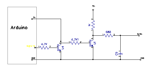
But for your project, use Grumpy Mike's schematic, and like I said, add another NPN to the NPN controlling the 0 - 10V output.
So in a nut shell.
(5V) (10V)
| Z
Z Z
Z | / -----------------O
| /---------VVV------|< |
---|< | \ ---
| \ v ,---,
v | |
| Z (GND)
Z Z
Z |
| (GND)
(GND)
ModAquatics:
I am sorry but I am kind of a newb here. Can you explain why the voltage would drop like that? I checked the data sheet for the transistor and it doesn't have a voltage drop like that.
Then use analogWriteReverse(pin, value) instead of analogWrite(pin, value).
Alternatively, you can program the chip to generate reverse pwm instead of normal pwm.
Alternatively again, connect the RC network to the Arduino PWM pin, then use an op amp in the non-inverting configuration to amplify the voltage by a factor of 2. This has the advantage that it is less sensitive to the load you put on the output. Also you can use a smaller capacitor.
dc42:
3. Alternatively again, connect the RC network to the Arduino PWM pin, then use an op amp in the non-inverting configuration to amplify the voltage by a factor of 2. This has the advantage that it is less sensitive to the load you put on the output. Also you can use a smaller capacitor.
This is the way I would go, simple op-amp voltage doubler
It is not a voltage doubler it is a times two amplifier. You need to be able to drive the load direct from the amplifier's output. Not a very good idea I would have thought.
Thanks Everybody. This was my first post on this forum. I am very happy to see so many responses (and quick!). It is refreshing to be on a forum with an active community of folks helping each other.
Mike, what if I used your original design but switched the NPN with a PNP transistor? Wouldn't that work? Hazardsmind suggested that earlier but I didn't realize that PNP's are not switched on unless the base is brought to 0v.
Any value used for the AnalogWrite function thta is outside the range will be rolled over. So 256 becomes 0 and -2 becomes 254. The only values (without modification) can be 0-255.