That's why the OP was asked to do some field work many posts back so we could see how things would work..
Placing the Opto 10 meters away takes the 9 Arduino output pins and Arduino GND out that far.
Might be a bit dodgy for noise problems back at the Arduino.
If as you mention there is a problem, the gate pull down resistor can be lowered to 1k.
Since there is no PWM involved here, a 100nF capacitor could be added also.
I think we want the long wires in the lower impedance circuit, that is the LED drive, where a bypass cap will not slow the switching time very much, but will keep interference away from the arduino.
You say is better to place the opto's and the mosfet as close to the solenoid as possible?
So only the arduino wires that run to the opto Led Anode pin will be long?
If I will make an effort to make the solenoid wire no more then 5 meter it will make any difference?
As mentioned, 9 output control wires and 1 GND wire taken out 10 meters ( ≈ 30 feet) is 300 total feet of cabling that can feed back noise to the micro controller pins.
This kind of situation should be avoided. If not, be prepared to possibly experience hardware failure from static; so much for using an opto isolator .
The OP has been requested to do testing many posts back but is avoiding to do so.
This thread has gotten too long, will let the experts take over.
Thank you very much for all your help @LarryD, I learned a lot . For me you are the expert!
I will do testing asap as I said and will be happy to post back the result!
Some small update: I finally got the chance to check one solenoid with 7 meter wire and it seems to work just fine, although the solenoid I was using and will use are 120mA @12V and not 800mA as I was thinking using before.
The fact I will use solenoid at much lower current could benefit me in some way? I will be able to use much smaller power supply and might will not need the fuses?
the less current the solenoids using the longer wire I could use or it is not make a difference?
For a given wire, the longer it is, the greater the voltage drop. The resistance of the wire is proportional to its length.
In addition, by Ohm's law, the greater the current, the greater the voltage drop across a resistor (the wire). So, lower current will help with total voltage drop.
One thing to keep in mind is that there is a link between solenoid coil current and its contact current rating. Usually, beefier contacts that are able to handle larger currents are heavier and require stronger magnetic fields to move them.
is there anything wrong with running the GND and the +VCC wires of the PSU that suppling the power for the MOSFET and Solenoids for a long distance such as 10-15 meters?
Edit: asking in another way - how long I can run a 12V PSU lines?
Some updates:
I made the circuits containing all 9 solenoids
the wire I'm using for the solenoid is between 2.5 to 3 meter.
some solenoid are stuck after a while. why this is happening? could it be the length of the wire is to long? the solenoid itself are not good quality? the resistor gate (6k8) is to high?
what shall I do in order to fix it? what shall I first check?
Do they have a plastic former where the plunger moves through. Maybe that melts and deforms after a while. 2.5watt continuous is a lot for a small solenoid like that. Solenoids are usually made for intermittend use.
Leo..
Hi,
Can you please post a circuit diagram of your solenoid control circuit?
Have you got 10K resistors between the MOSFET gate and source pins?
You will need them to stop the gate from holding the MOSFET on if the gate is disconnected, or at the end of a long signal line.
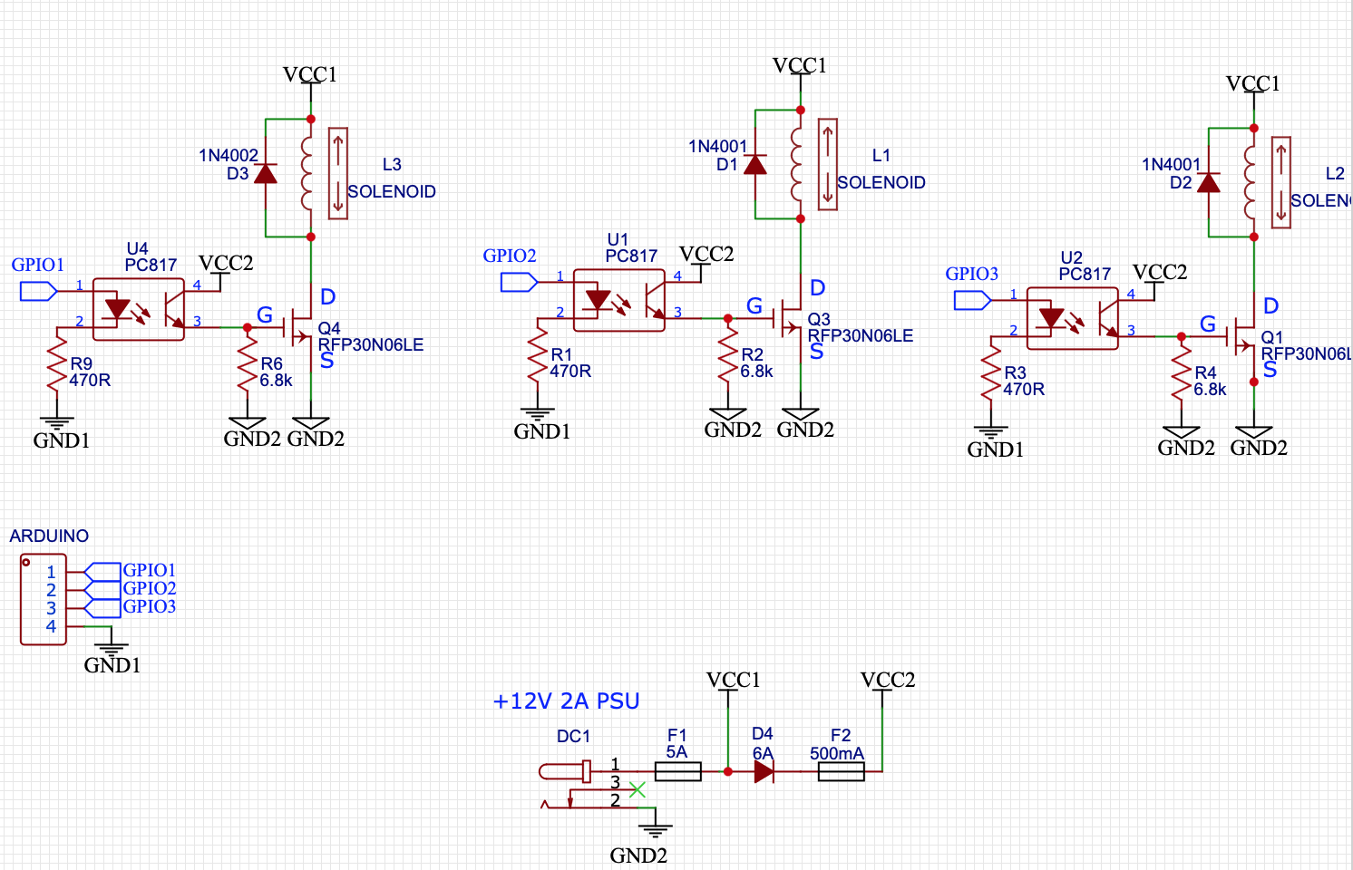
here is the updated schematics (3 solenoids out of 9 in total).
One (important) observation I notice is that when the solenoids are struck against an object (in which this is how they will behave as it is a part of music concert), the solenoid in not stuck and rather working as intended. when the solenoids are working without striking an object some of them are stuck in one position or another.
I will check it the moment I will be at the studio with the circuit. I check it by placing the + prob of the multimeter at the Drain terminal of the MOSFET and the ground prob of the multimeter (is it the right term?) on the Source terminal of the MOSFET ?