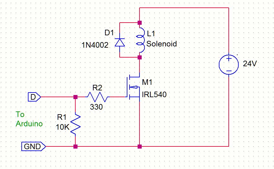
i am in making of a project, that consists of an Arduino Mega and a push pull solenoid, which is controlled via the Arduino. I have a bunch of opto-isolating modules and IRL540N MOSFET`s. The solenoid coil has a resistance of 1,55 Ohm, which at the supply voltage of 24V draws around 15-16 Amps. Note that the coil should somehow be able to stay activated for a few second, which probably doesn´t benefit the Mosfet all that much. Is there a way that this could work with the components provided? I would like for some opinon but much more a circuit from an expert... As I am very novice and my skills are limited, attempts in the past have failed with a broken MOSFET. I don´t have the old circuit anymore, but i would like to make this work, if it is possible. If not, would a SSR be more suitable?
Thank you in advance for all the advice and help!!
The Drain-Source On-State Resistance of the IRL540N is: Rds(on) @ Vgs = 5.0 V is 0.077 ohms
The power dissipated by the MOSFET is Current^2 x Rds(on) = 16^2 x 0.077 = 20W!!!!
That is a lot of heat, even for a few seconds.
So, you will need a heat sink for the MOSFETs and possibly a fan depending on how many MOSFETs you have.
I am very novice when it comes to datasheet information. So, is the IRL540N a MOSFET, capable of direct control via uC output, or do i need a special circuit for this? If so, what kind of circuit would be recommended?
The IRL540 is a poor choice for a 15A load. RDS(on) is 0.077 Ohms with 5V on the gate, meaning the MOSFET package dissipation will be around 17 W, and it will quickly burn up unless you have an excellent heat sink.
Datasheet says the solenoid rated current is 3A, not 15A.
If you go by the coil resistance (58 ohms) that's about 400mA @ 24V dc.
I get about 10W for I^2*R = (0.400)^2 * 58 = 9.93W.
The product page link gives specs for only the 220 VAC solenoid.
If the following is correct, then the solenoid will be dissipating 360 W when activated. Use it to heat your room, for a very short while.
solenoid coil has a resistance of 1,55 Ohm, which at the supply voltage of 24V draws around 15-16 Amps. Note that the coil should somehow be able to stay activated for a few second,
Looking at your solenoid and similar solenoids there is no way I see what you have, running with a 24 VDC coil drawing 15 or 16 amps. You would be looking at a coil wound with AWG 14 (1.628mm) wire give or take. How did you come up with a coil resistance of 1.55 Ohms? Something just does not seem right about a 16 Amp DC coil. I would make real sure as to coil current including maybe actually measure it before I would worry about driving or controlling it.
I know it is all very weird, however, on the coil itself (or on the product if i may say so) it is written, that te coil resistance is 1,55 Ohm. And when I connected it to a bench power supplpy for testing it indeede indicated 15 Amps of current draw. The full current draw only occur if the coil is being held pressed, if i only press the switch to trigger and release, it doesn´t exceed 9 Amps (or is the initial spike so huge the analog A-meter doesn´t even show the value?
So i measured the actual resistance of the coil....it is even smaller, varying from 1,2 - 1,4 Ohms with cca 1.5m of 13 AWG wire...it is redicolous i know, but this is what i have and has to be somehowe done...would a SSR be more suitable and easy to connect?
Hi,
The link in post #6.
It is advertised as an DC solenoid but all information is for AC solenoid.
So no matter what coil voltage you order, it will be an AC rating and not DC.
Open frame style, open coil form, built-in mounting board, pull push type AC electronmagnet.
Used widely in banking ATM, vending machines, electronic appliances, embroidery machines, intelligent lock, juice bread maker, textile machines, cash register or other automatic control devices.
So would this mean that this solenoid would work with both AC and DC? Because then the current with AC would be 10 times smaller, meaning i could use a standard 10A relay to trigger it yes?
With AC it's the inductive reactance at line frequency (50 or 60 Hz = ~ 73Ω) that limits current, with DC applied there is no such limiting. Current will be V / R.
Meaning something like this...DC voltage -> I = V/R = 24V / 1.55 OHm (Coil resistance) = 15,5A
AC voltage -> I = V / R = 220 / (73+1,55) Ohm (Reactance + coil resistance) = 2,95A ??
If this is correct, a standrad switch would even be good enough without any possibility of danger?
Further more, uC controlling such a coil with a standard relay would also work just fine yes?
Are there any safety measures that i should consider? Fuse, circuit breaker etc..?
If the marking on the coil is 1.55 ohms and you measure around 1.5 with an ohmmeter and it draws 16A with 24V applied, then how could it be anything but 1.55 ohms. Why would anyone think otherwise??
Considering it has a 3kg pull force I wouldn't consider 16A @ 24V to be unreasonable.
That solenoid is more than likely designed for intermittent operation, something like 5 seconds on and 60 seconds off.
Because it is a chinese product, so the marking is never EVER correct..They do put in some description, however in my experience it is always to consider some room for different numbers in reality....that is why I am extra carefull. I do actually need a high pull force unfortunately, that is why I need to make this work somehow.