Controlling 12V DC Voltage...

Hi all

First post. Sorry if it's in the wrong format or wrong place. I'm a software developer by trade, electronics and circuitry are new to me.

I have an external 12V/2A DC PSU. I'd like to be able to vary the voltage of the PSU in small increments between 5V and ~12V. I guess I can use the PWM output to drive something, but no idea what that something would be. So, at 0% PWM we'd have 5V and 100% we'd have ~12V...7V range, say if the steps were 0.7V per 10% of PWM. Is this achievable?

Any advice or pointers would be welcome.

EDITED TO ADD - The reason I'd rather not use PWM.

See here in the Blower Settings section. This is why I'd rather use voltage control than PWM.

"Output Mode Pulse / Voltage (v11 and above) - Pulse mode uses a continuous series of low speed (490Hz) 12V power pulses to regulate the blower speed. Voltage mode is available on HeaterMeter v4.2 hardware and enables step-down circuitry to produce a constant voltage on the output pin between 5V and 12.1V. Voltage mode is more precise with a linear output curve, and runs the blower more quietly than pulse mode"

Many thanks

Post the circuit diagram, so we can see if it's possible.
Leo..

Wawa:
Post the circuit diagram, so we can see if it's possible.
Leo..

Thanks Leo. Unfortunately I don't have a circuit diagram. I just know what I need to achieve at the end of it!

I have an Arduino Uno...a 12V 2A DC PSU...a 12V DC Blower.

I need to be able to pass between 5-12V into the Blower, the voltage to be controlled ultimately by the software running on the Arduino. I have no idea how the middle bit looks or works. Hence asking here.

May be better asking on a dedicated electronics forum. Sorry!

say if the steps were 0.7V per 10% of PWM. Is this achievable?

I think you are confused. PWM is not analog. There are no steps. There are no voltage levels . There is only duty cycle. If you want to talk about duty cycle you can't equate that to voltage levels. Without a schematic there is no way to know what you are talking about.

I need to be able to pass between 5-12V into the Blower, the voltage to be controlled ultimately by the software running on the Arduino. I have no idea how the middle bit looks or works. Hence asking here.

May be better asking on a dedicated electronics forum. Sorry!

It sounds like you need a low side switch.

I have a news flash for you. It doesn't get any more dedicated that this.
You aren't going to find any forum with more knowable members in the area of electronics.

Take a look at this thread.

or this

Try one of these with a decent heatsink

Don't control the supply.
Control the blower (with PWM).
Post a link/description/picture of the blower.
Leo..

Yes it is. I would suggest watching Eevblog psu design as it goes through the basics including pwm control.

raschemmel:
I think you are confused. PWM is not analog. There are no steps. There are no voltage levels . There is only duty cycle.

Hi there raschemmel. It depends on application or situation right? If using PWM to control the speed of a motor, the voltage waveform at the PWM final output (to the motor) is analog. Binary levels, but not for sending data.

If using PWM for communications..... sure, the 1's and 0's can be stored (binary, 1 bit digital) - such as the output of a delta modulator or a delta sigma modulator. When demodulating... the PWM signal is analog, and then filtered.

I know what you mean though!

See here in the Blower Settings section. This is why I'd rather use voltage control than PWM.

"Output Mode Pulse / Voltage (v11 and above) - Pulse mode uses a continuous series of low speed (490Hz) 12V power pulses to regulate the blower speed. Voltage mode is available on HeaterMeter v4.2 hardware and enables step-down circuitry to produce a constant voltage on the output pin between 5V and 12.1V. Voltage mode is more precise with a linear output curve, and runs the blower more quietly than pulse mode"

Hi there raschemmel. It depends on application or situation right? If using PWM to control the speed of a motor, the voltage waveform at the PWM final output (to the motor) is analog. Binary levels, but not for sending data.

If using PWM for communications..... sure, the 1's and 0's can be stored (binary, 1 bit digital) - such as the output of a delta modulator or a delta sigma modulator. When demodulating... the PWM signal is analog, and then filtered.

I'm afraid I would have to give you a "0" on that answer (I won't address the communications aspect since it has no relavance.) No, PWM is not analog. PERIOD. And no it does not LOOK like analog and furthermore it is not output to a motor. A motor is switched with PWM using a LOW side switch (transistor or mosfet).
I won't even address the fact that a VFD (Variable Frequency Drive) most certainly can send pwm to a motor (across two wires) because VFDs are expensive and the likelyhood that anything said about a VFD would be of any help to a poster is slim to none. I have used a 35 kW VFD (DANFOSS). As far as almost any poster here on the forum, dc motor control is going to be about switch the motor with a transistor or mosfet . Why, because obtaining a variable voltage 10A 12V power supply is going to be difficult and expensive. If the OP wants to use voltage control then he barking up the wrong tree posting here on the forum because what he needs is a credit card and a Google search. and that's all he needs. He doesn't need to post on the forum. Posting on the forum is his only option if he cannot afford the variable voltage 10A adjustable bench LAB power supply and is willing to switch the motor with a 95 cent mosfet and a good heatsink
(see previous post with heatsink link).

Getting back to the PWM waveform. The below is a 16 kHz pwm signal across a 12V motor driven by the same mosfet linked above. As you can see, it in NO WAY looks analog. There is absolutely nothing remotely analogISH about the waveform. It is CLEARLY a PWM with the slight changes I mentioned.

I will add that if the OP wants to open a discussion about a "roll your own" (DIY) 12V, 10A variable power supply , that option is available but must be approached with understanding that it would depend totally on the effectiveness of the heatsink used. The right low RDS(on) mosfet would go far in reducing the required heatsink size and mass. A variable voltage 10A switching power supply would probably be the best bet but as the OP has noticed, it is possible a motor can generate noise from the power supply used or the method of switching. Would a blower motor make noise if powered from a variable switching supply ?
I have no idea but it wouldn't surprise me.

+1 no price tag :slight_smile:

raschemmel:
I'm afraid I would have to give you a "0" on that answer (I won't address the communications aspect since it has no relavance.) No, PWM is not analog.

raschemmel, you can also give Texas Instruments a "0" too. An analog "0".

click here on this link

raschemmel, you can also give Texas Instruments a "0" too. An analog "0".

I clearly stated I would not address the communications aspect since it has no relavance.
If you want to link a 10A analog PWM circuit then we can talk. The op amp circuit you linked has no relavance and once again I remind you we are discussing pwm of a motor, not communications PWM.
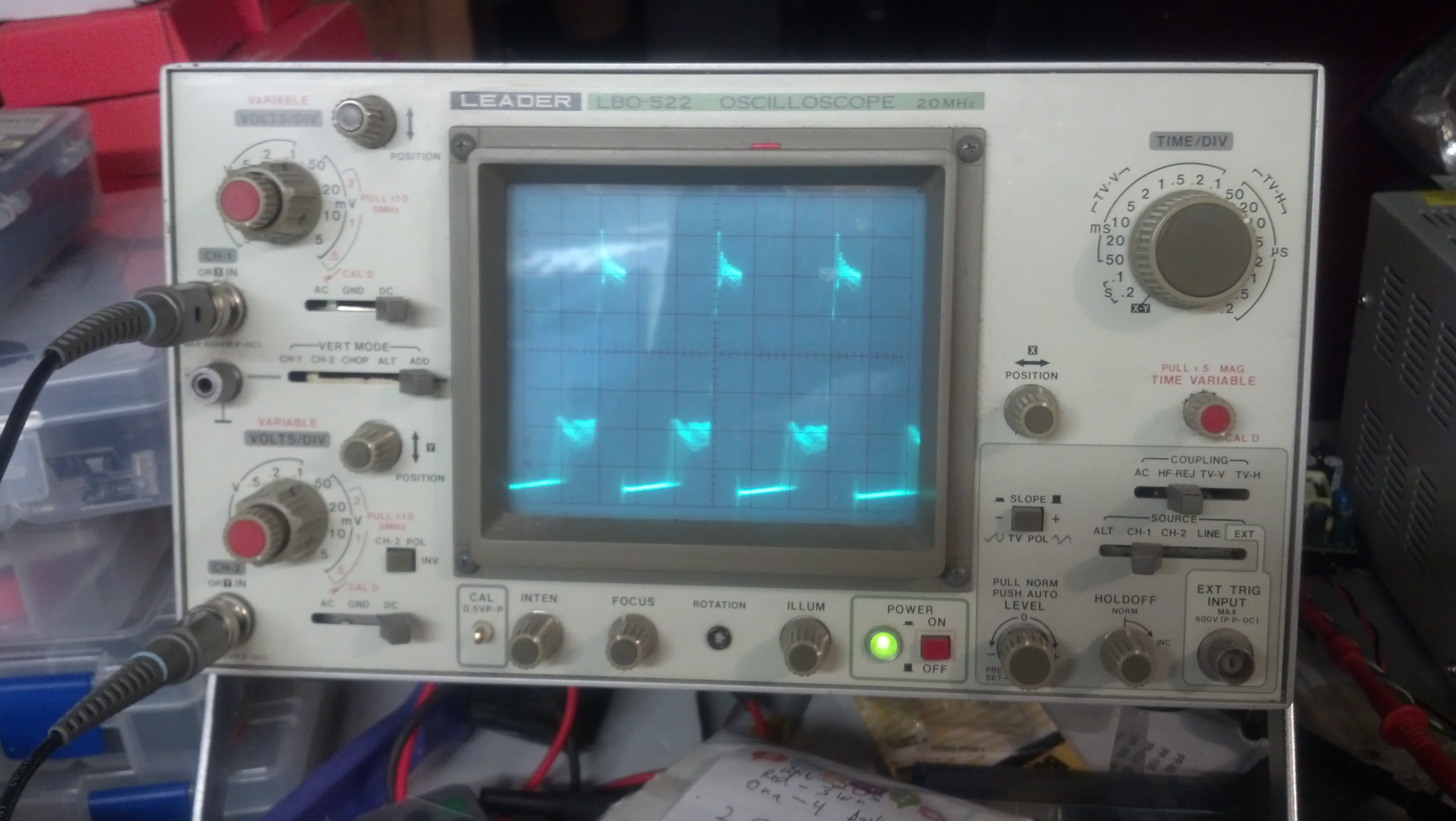
Please try to stay on topic. The OP has a 10A blower motor. Your TI communications circuit is not going to do him any good (and I said I wouldn't discuss communications). You can see the waveform on the scope, so unless you want to post a scope screenshot of a MOTOR PWM waveform that LOOKS ANALOG, you still get a "0".

The fact that you think the PWM is analog because TI's ANALOG circuits division designed a circuit that outputs PWM (again, not analog) is amusing. You need to review the definition of analog. That communications circuit is outputing PWM, which (once again) is not analog.

This circuit utilizes a triangle wave generator and
comparator to generate a pulse-width-modulated
(PWM) waveform with a duty cycle that is inversely
proportional to the input voltage. An op amp and
comparator generate a triangular waveform which is
passed to the inverting input of a second comparator.
By passing the input voltage to the non-inverting
comparator input, a PWM waveform is produced.
Negative feedback of the PWM waveform to an error
amplifier is utilized to ensure high accuracy and
linearity of the output

That circuit is an ANALOG to PWM converter.

This circuit utilizes a triangle wave generator and
comparator to generate a pulse-width-modulated
(PWM) waveform with a duty cycle that is inversely
proportional to the input voltage

Input voltage: -2 V to +2 V, dc coupled
 Output: 5 V, 500 kHz PWM

Look up ANALOG. Or, better yet, look at an audio signal or an analog signal from a sensor or the voltage on a pot as you turn it.

while your at it, look up PWM.
The definition is in the name : It is a PULSE , and the WIDTH of the PULSE is MODULATED.
(it could also be +/- voltage pwm)

A PWM signal is still PWM , even when generated by analog chips, like op amps.

I guess you could ask "So why is a PULSE not ANALOG ?"
(hint: because it's a pulse ?)

@OP,

Pulse mode uses a continuous series of low speed (490Hz) 12V power pulses to regulate the blower speed

Why are you using 490 Hz instead of 16 kHz ?

// Arduino UNO DDS

#include <PWM.h>

int32_t frequency_9 = 12000; //frequency (in Hz)
int32_t frequency_3 = 16000; //frequency (in Hz)
 

void setup()
{

InitTimersSafe(); 

SetPinFrequencySafe(9, frequency_9);
SetPinFrequencySafe(3, frequency_3);
 
}

void loop()
{
 int val = analogRead(A0);
 val = map(val, 0,1023,0,100);
 
 int dutyC =512; // Duty Cycle 0 (0%) - 1023(100%)
 pwmWrite(9, dutyC / 4);
 pwmWrite(3, val);
 delay(30);
 
 }

+1 no price tag

It was $95 if anyone was intereseted. (HALTED SPECIALTIES, SUNNYVALE, CA, USA)

raschemmel:
I clearly stated I would not address the communications aspect since it has no relavance.
If you want to link a 10A analog PWM circuit then we can talk. The op amp circuit you linked has no relavance and once again I remind you we are discussing pwm of a motor, not communications PWM.

You told a forum member that PWM is not analog. I gave you a hint that PWM in motor controllers does not involve sending data .... so obviously it is not digital for a start. Also, you don't even need a computer/micro-controllers to generate PWM.

The reason for showing you the web-link is to say to you that analog PWM signals certainly exist (they have existed for years and years) - to correct you about your incorrect comment - recall your comment: "I think you are confused. PWM is not analog."

If you want to link a 10A analog PWM circuit then we can talk.

No need to talk to me about it. There are many links to commercially available 10 Amp PWM controllers. I don't need to add links...since there are many that you can easily find. Note once again - the PWM signal on the output stage is analog.

As for the OP's new info regarding a blower, I do agree (with the OP) that it should be better to just supply the motor with a dedicated DC voltage supply. It can be a digitally-controlled DC voltage supply.

Southpark:
As for the OP's new info regarding a blower, I do agree (with the OP) that it should be better to just supply the motor with a dedicated DC voltage supply. It can be a digitally-controlled DC voltage supply.

Is there a board I can buy or a circuit I can build to achieve this?

Many thanks

@Southpark,

You are still confused. Digital does NOT (necessarily ) equate to data and more importantly, you are confused because you still do not understand that PWM and data may or may not have something to do with each other but the reason PWM is not analog is that the transition is from rail to rail (is: 0V to 5V, or -5V to +5 or -15V to + 15V) whereas analog is anything that does not consist of discrete predetermined voltage levels where the signal is clearly switching from one level to the other level and returning to that level again. Analog has no such repeatable On/Off levels but rather , like an audio signal or a sensor signal is more or less unrepeatable though it could be repeatable as long as it is not switching from one rail to the other like PWM, , which does not stop at any point in between the two rails.
Why do you keep trying to associate PWM with analog or digital when it is neither ?
Digital is 1s and 0s. PWM is NOT 1s and 0s. It is a variable duty cycle. Analog is non discrete voltage. This is basic electronics 101. ( did you skip that class ?)

I can't help thinking you think that if something is not digital it is analog and vice versa.
PWM is neither.

No need to talk to me about it. There are many links to commercially available 10 Amp PWM controllers. I don't need to add links...since there are many that you can easily find.

If they're so easy to find then why can't you find one ? (and link it?) (talk is cheap)

As the following link explains, "ANALOG PWM" is PWM generated (and controlled) by analog circuitry whereas DIGITAL PWM is PWM generated (and controlled) by digital circuitry. In BOTH cases, the OUTPUT is PWM , which is NOT analog, no matter HOW you make it.
Why ? Because it is PWM which by definition is not analog. It's like asking why is an orange a fruit and not a vegetable ?

Pulse Width Modulation, or PWM, is a technique for getting analog results with digital means. Digital control is used to create a square wave, a signal switched between on and off.

That means it is a way to control the voltage across a load by switching the source on and off.
The signal itself is digital (high/low as opposed to 1/0) but the resulting voltage across the load is a variable (or analog) voltage.

To say that PWM is analog because the result is analog is nonsense.

PWM

analog-vs-digital-pwms

Again I ask you, does the waveform in the photo below look like ANALOG to you ?

@OP,
I gave you a link. Google "computer controlled 10A variable power supply "or "10A motor speed control". I 'll look when I get time today. You don't have a DAC on the UNO so if you want an analog voltage controlled power supply you'll have to use an RC LPF to covert pwm to analog (why is that necessary Southpark if pwm is already analog ?)

You might find a motor control that accepts pwm. Finding a pwm controlled variable 10A power supply is going to be more difficult.

Sorry, I missed it in the rest of the stuff...which mostly went above my head.

I already have a 12V DC power supply. Was hoping I could somehow do something with the PWM signal from the UNO and some MOSFETs (no idea...just what I've read) to vary the voltage which is passed to the Blower.

Thank you for your help so far. I'm trying to learn :slight_smile:

ETA - And for the record, no issue at all putting my hand in my pocket if it's the right/best thing to do...as above, trying to learn about a new subject...so it's more about the journey than the result.

I already have a 12V DC power supply. Was hoping I could somehow do something with the PWM signal from the UNO and some MOSFETs (no idea...just what I've read) to vary the voltage which is passed to the Blower.

That is definitely doable. What is more difficult/expensive is programmable variable voltage power supply.

I will try to find one of the latter for you but if you want to pwm the motor with a mosfet that is very straightforward.
pwm-generation-and-control-using-arduino

Arduino PWM

NOTE: The motor should have a suitable diode across it to prevent back EMF from destroying the mosfet.
** The cathode (banded end) of the diode should be connected to the + motor terminal and the**
** anode to the - motor terminal.**

You still have not posted any details about your blower motor.
If you can provide those details, you can contact the ROBOSHOP and ask them what controller would work best to control your motor with an UNO.

I have a few Blowers lying around, including

https://www.proto-pic.co.uk/blower-squirrel-cage-12v.html

Is this circuit (middle right of the image) controlling with PWM or 5-12V? This is the project referenced above, and now in my OP, discussing 5-12V stablity vs straight up PWM control stability.

http://capnbry.net/linkmeter/pcb/hm-4.2/HeaterMeterPi.png

Is this circuit (middle right of the image) controlling with PWM or 5-12V? This is the project referenced above, and now in my OP, discussing 5-12V stablity vs straight up PWM control stability.

I think you are confused. Under NO circumstance would you EVER be controlling the motor with the 5V that powers the arduino. The motor voltage is simply whatever voltage you choose to use for the motor power, which, in any PWM circuit , is Vcc for the motor, not the Vcc for the arduino. Since you are inexperienced, from this point forward, we will refer to the arduino 5V as "+5V", and the motor power source as "VMOTOR" or Vm. The motor + wire goes to Vm + and the motor - terminal goes to the DRAIN of the mosfet. The SOURCE of the mosfet goes to Vm-. Vm- goes to arduino GND. Arduino output pin goes to the mosfet GATE. I already posted code for a 16 kHz pwm sketch that reads a potenitiometer connected to A0. If you want to convert that sketch to fully programmable you need to remove the pot and connect an RC LPF (4.7 k ohm/ 4.7 uF) between a PWM output pin and A0 and write the code to control the PWM duty cycle which will be read by A0 and converted to a motor speed.

Secondly, your reference to 5 to 12V stability is only relevant if you have a variable voltage power supply. If you did, you COULD set the supply for 5V but it would be coming from the programmable power supply and not from the arduino 5V. You could adjust the motor voltage from 5V to 12V if you had that kind of supply, which currently , you don't.
Which , you currently don't and if you want to buy one will probably be expensive. You cannot discuss that unless you are prepared to do that. All you have right now is arduino PWM control of a mosfet switching the motor. This, as I said is quite doable but you need to pay attention to the need for a heatsink because if you don't you will simply damage the mosfet. If you had a low enough RDS(on) mosfet you could use a smaller heatsink.
This is the type of heatsink I recommend. If you do not use one that looks EXACTLY like this one you must tell us (show us) what type you are using BEFORE you attempt to power the blower to avoid damage to the mosfet.