NO.
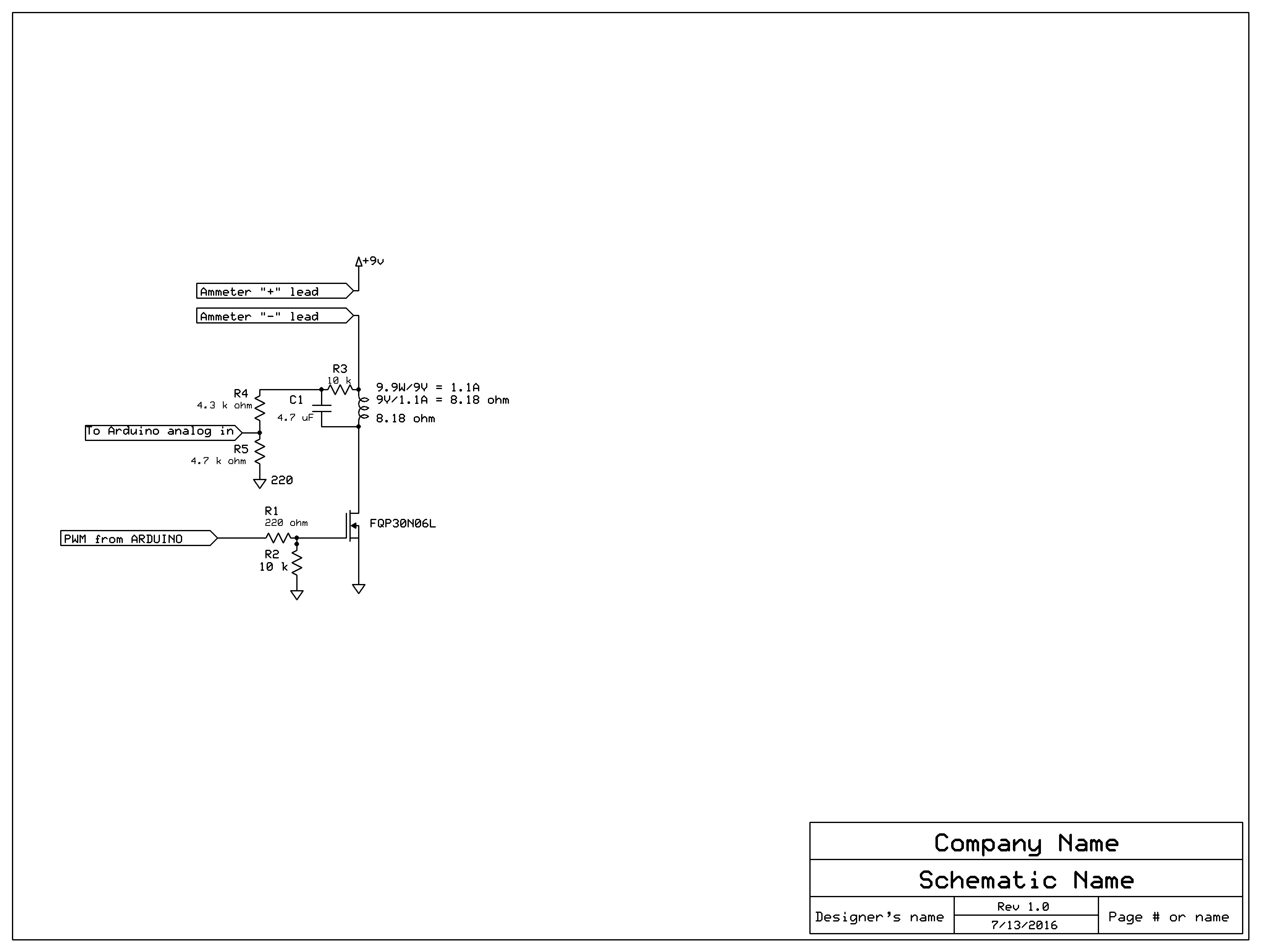
Your circuit schematic has numerous errors. see attached.
(the 10 k resistor and cap were in the wrong place)
For clarification, previous reply was addressed to Runaway Pancake.
Given that someone else posted the power rating of your pad (which you failed to include) as 9.9W, I have taken this rating to be correct and calculated accordingly . If you have information to contrary please advise.
Given P = 9.9W,
I must be P/V = 9.9W/9V = 1.1 A
Given I = 1.1 A,
R must be V/I = 8.18 ohms
Your 9V power supply must be rated for at least 1.5A
You have provided NO information.
You have NOT provided ANY ratings or specs for heating pad.
You have NOT provided ANY part number for MOSFET.
Without the part number of the one you said is recommended, I have temporarily supplied a part number
You have NOT provided ANY details about your 9V power supply (current rating etc)
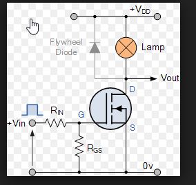
The ameter goes in series between the 9V power source and the load (the heating pad)
The heating pad goes between the ammeter and the mosfet drain.
I have shown where to connect ammeter "+" and "-" leads.
Current and resistance are calculated from the 9.9W rating posted by someone else since you provided no information.
Voltage divider values should yield 4.7V at 100% duty cycle (pwm value = 255)
I like to ask about the duty cycle. The voltmeter will measure the voltage, but for the x-axis what will this value be?
Not sure if you understood my previous post about plotting voltage with respect to duty cycle.
Obviously this can only be done if you have the RC LPT to convert the pwm (on/off waveform) to analog voltage.
Y Axis (Voltage)
^
|
|
|
-----------------> X Axis (duty cycle)
Duty cycle = 0, Voltage = 0 etc
9V/2 = 4.5V
100% duty cycle /2 = 50% duty cycle
THUS ==> duty cycle = 50% = Voltage = 4.5V
DO THE MATH
9V/255 "steps" = 0.03529411764705882352941176470588 Volts/per step.
Thus Voltage = [duty cycle} * [255 counts] * [0.03529411764705882352941176470588 Volts per count]
SO , 50% Duty cycle * 255 counts = 127.5 counts (must be integer) => 127 counts
127 counts * 0.03529411764705882352941176470588 Volts per count = 4.4823529411764705882352941176471 Volts.
Thus if you read the analog input and multiply the analog counts by 4.7V/1023 (0.0045943304007820136852394916911 Volts) you will get the voltage.
so 1023 /2 = 511.5 (must be integer) => 511
511 * 0.0045943304007820136852394916911 = 2.3477028347996089931573802541544 (half of 4.7V)
Keep in mind, the above calculations are based on a full scale voltage of 4.7V at 100% duty cycle due to the voltage divider values.
Normally the analog range is 0 to 5V. That doesn't apply for you because your range is 0 to 4.7V.
datasheet for your mosfet
If you use Clear Terminal instead of the arduino IDE serial monitor, you can capture the serial prints of the duty cycle and analog voltage measured and then after cycling through all 255 counts you can click
"File\Save buffer to file " in the Clear Terminal window and save the serial output , which you can use to plot the values in Excel (analog voltage with respect to duty cycle)
