Controlling 18v motor with mosfet

My end goal is to be able to control a 18v at variable speeds using an arduino. Originally, I was planning to use a relay and only have on/off control, however I recently found out what a mosfet is and being able to control the speed would be very useful.

My current plan is to use the following circuit diagram with an arduino nano and a IRLZ44N mosfet.


image backup link

When I connected the motor straight to the batteries I measured 1 amp of current

IRLZ44N datasheet

A few questions I have

  1. Will this circuit work? I want to make sure that I don't blow the arduino or anything

  2. Will the IRLZ44N work in this application?

  3. Can I use PWM to control the speed of the motor? Ex. would analogWrite(7, 128) run the motor at half speed?

  • Place a kickback diode across the motor.

  • 328 has these pins for PWM 3, 5, 6, 9, 10, and 11

Move the upper end of the 10k resistor to the controller output pin.

1 Like

Speed will depend on motor load, heavier load, lower speed.

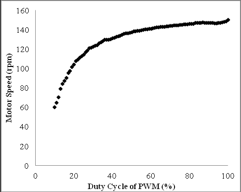
No, motor speed versus PWM typically looks something like this (for no load on the motor shaft). Below some percentage value of PWM, it won't even start moving.

Move the upper end of the 10k resistor to the controller output pin.

So that it is on the left side of the 200 ohm resistor? With the other side still connected to ground

Yes. The 10k resistor is there for the Arduino pin, not for the mosfet.
The resistor keeps the Arduino pin LOW during boot, when the pin is still undefined.
Leo..

Will a kickback diode across the motor be enough, or will I need another one across the mosfet as well?

You only need a diode across the motor.
Diodes across FETs are only useful in a H-bridges, not across a single FET.
Leo..

Hi,
To clarify all that has been suggested;

Tom... :smiley: :+1: :coffee: :australia:

2 Likes

This topic was automatically closed 180 days after the last reply. New replies are no longer allowed.