Controlling 2 DC Motors Via PWM by using L298N-h bridge driver

Hi. I have followed this tutorial in order to control 2 DC motors. The only difference is that I have Arduino Mega 2560.
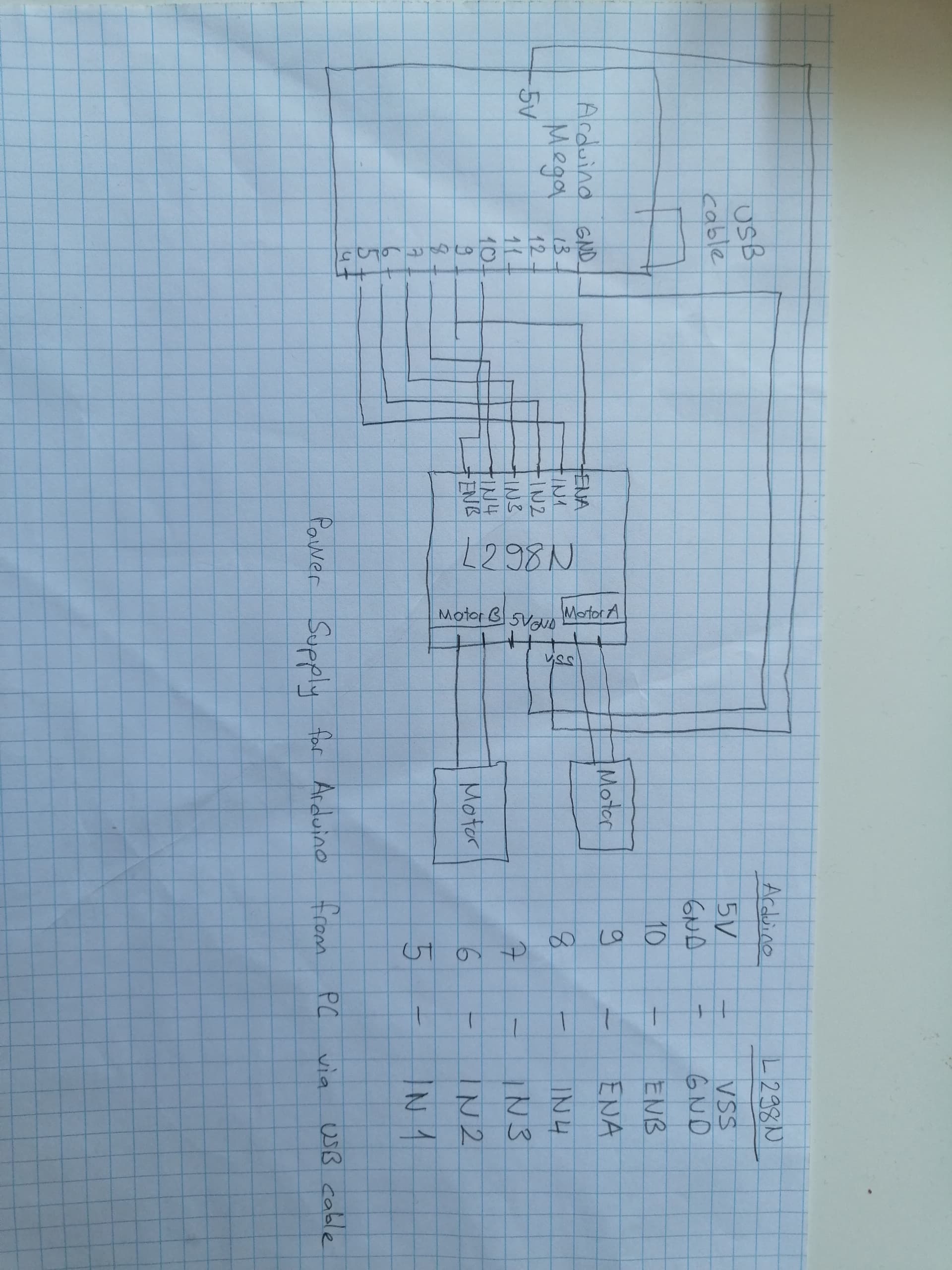
The connections are
enA = D9
IN1 = D5
IN2 = D6
IN3 = D7
IN4 = D8
enB = D10
VSS = 5V from Arduino
GND = GND from Arduino
MotorA = First motor
MotorB = Second motor

The problem is that there is no voltage so motors are not turning. At the same config without changing connections, when I changed enA = 11 (connection is 10), the motors are working separately. I have not been able to find explanation of the behavior. Thank you in advance.

My code is here:

// Motor A connections
const int enA = 9;  // when it is 11 at the same config it is working separately 
const int in1 = 5;
const int in2 = 6;
 
// Motor B connections
const int enB = 10; 
const int in3 = 7;
const int in4 = 8;
 
// Set the speed (0 = off and 255 = max speed)
const int motorSpeed = 255;
 
void setup() {
  Serial.begin(9600);
  // Motor control pins are outputs
  pinMode(enA, OUTPUT);
  pinMode(enB, OUTPUT);
  pinMode(in1, OUTPUT);
  pinMode(in2, OUTPUT);
  pinMode(in3, OUTPUT);
  pinMode(in4, OUTPUT);
 
  // Turn off motors - Initial state
  digitalWrite(in1, LOW);
  digitalWrite(in2, LOW);
  digitalWrite(in3, LOW);
  digitalWrite(in4, LOW);
 
  // Set the motor speed
  analogWrite(enA, motorSpeed); 
  analogWrite(enB, motorSpeed); 
}
 
void loop() {
 Serial.println("Main loop");
  // Go forwards
  go_forward();
  delay(3000);
 
  // Go backwards
  go_backwards();
  delay(3000);
 
  // Go right
  go_right();
  delay(3000);
 
  // Go left
  go_left();
  delay(3000);
 
  // Stop
  stop_all();
  delay(3000);
}
 
/*   
 *  Forwards, backwards, right, left, stop.
 */
void go_forward() {
  Serial.println("Forward");
  digitalWrite(in1, HIGH);
  digitalWrite(in2, LOW);
  digitalWrite(in3, HIGH);
  digitalWrite(in4, LOW);
}
void go_backwards() {
  Serial.println("Backward");
  digitalWrite(in1, LOW);
  digitalWrite(in2, HIGH);
  digitalWrite(in3, LOW);
  digitalWrite(in4, HIGH);
}
void go_right() {
  Serial.println("Right");
  digitalWrite(in1, HIGH);
  digitalWrite(in2, LOW);
  digitalWrite(in3, LOW);
  digitalWrite(in4, HIGH);
}
void go_left() {
  Serial.println("Left");
  digitalWrite(in1, LOW);
  digitalWrite(in2, HIGH);
  digitalWrite(in3, HIGH);
  digitalWrite(in4, LOW);
}
void stop_all() {
  Serial.println("Stop All");
  digitalWrite(in1, LOW);
  digitalWrite(in2, LOW);
  digitalWrite(in3, LOW);
  digitalWrite(in4, LOW);
}

Maybe the "enable" pins are actually "not enable" pins and writing 255 to them disables the outputs. Change const int motorSpeed = 255; to const int motorSpeed = 128;. If the motors then work, use 0 for full speed and 255 for stop.

No, unfortunately it did not change. The led indicators on the driver are lid correctly but motors are not turning.

I'm stumped. I can't think of any way that, if properly wired and powered, the sketch and motor drivers won't drive the motors.

Grab pen and paper and make a drawing! Reading the following replies the request is needed.

Which DC motor?

Hi, @oguzkah
Welcome to the forum.

Thanks for using code tags when you posted your code. :+1:

As well as a hand drawn circuit can you please post some images of your project so we can see your component layout?

What are you using for the motor power supply?
Have you got the jumpers set correctly?

Thanks.. Tom.. :smiley: :+1: :coffee: :australia:


Here is the connections. I cannot upload the pdf since I am a new user.

Motors are DC Geared Motor with encoder-SJ02 (6V 160RPM 120:1).

Hi,

Can you please post a link to spec/data?

Thanks.. Tom.. :smiley: :+1: :coffee: :australia:

Sure, there you go. motors

Hi,
Your motors;

Specification

  • Gear ratio: 120:1
  • No-load speed @ 6V: 160 rpm
  • No-load speed @ 3V: 60 rpm
  • No-load current @ 6V: 0.17A
  • No-load current @ 3V: 0.14A
  • Max Stall current: 2.8A
  • Max Stall torque: 0.8kgf.cm
  • Rated torque: 0.2kgf.cm
  • Encoder operating voltage: 4.5~7.5V
  • Motor operating voltage: 3~7.5V (Rated voltage 6V)
  • Operating ambient temperature: -10 ~ +60℃

Tom... :smiley: :+1: :coffee: :australia:

Hi,
Can you please post a proper circuit diagram?
An image of a hand drawn circuit will be fine, unfortunately the Fritzy picture is just a crisscross of coloured wires.
Please include power supply, component names and pin labels.

An image of your project would be good as well, so we can see your component layout.

Thanks.. Tom.. :smiley: :+1: :coffee: :australia:

If this is correct:

image

... then the L298 datasheet explains why there's no volts at the motor:

The L298 is a really cr@p choice for low voltage motors. If your motors were say 30V odd, then the losses are relatively less, but if you start with only 5V....

I recently had exclty the same problem with my H bridge but trying everything the only solution i found was if you conect the pins 9 and 11 it works


the solder in this one it's not great but it's just for reference
First try to link them with a screwdriver or something similar , if it works solder it if it doesen't i don't know what's happening.

That is shorting "Enable B" to +5V. That would override any speed signal from the Arduino and possibly cause the Arduino to overheat.

This topic was automatically closed 180 days after the last reply. New replies are no longer allowed.