Controlling 3V~ mini vibration motors with Arduino and bjt

I would like to control 32 mini vibration motors rated 3V 50mA each.
I would like to control each group of 4 motors with 1 pwm pin.

the motors will be located around 10/15 meters away from the Arduino. In that case - should I:

  1. add optocoupler? if yes how to wire it?

  2. add a fuse?

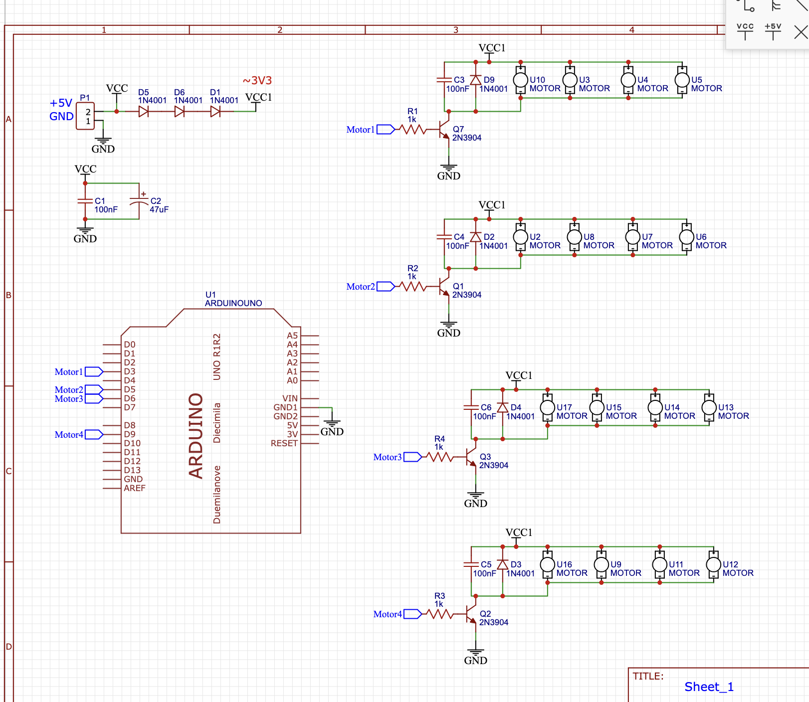
  3. if using 32 motors in total the total consumption is 1.2A' if we take x1.5 margin it is rated to almost 2A. in that case the 3x 1N4001 diode that drop the voltage from 5 to 3V is rating will not be good right? what diode I should use instead?
    any other tips?

Here is my schematics (16 out of 32 in total):

Here is my Arduino code (it has some other parts that are not in that schematics)

const int NUM_PWM_MOTORS = 4;
const int pwm_motor_pins[] = { 3, 5, 6, 9, 10, 11 };
const char pwm_motor_ids[] = { 'U', 'V', 'W', 'X', 'Y', 'Z' };


//digital pins connected to solenoids 1 - 9:2,4,7,8,12,13,A0,A1,A2//

const int NUM_DIGITAL_MOTORS = 9;
const int digital_motor_pins[] = { 2, 4, 7, 8, 12, A0, A1, A2, A3 };
const char digital_motor_ids[] = { 'A', 'B', 'C', 'D', 'E', 'F', 'G', 'H', 'I' };
unsigned long heartbeatMillis;
int heartbeatLED = 13;

//pedal//
int SW;
int exSW = 0;
unsigned long previousMillis = 0;
unsigned long currentMillis = 0;


void setup() {

  for (int i = 0; i < NUM_PWM_MOTORS; i++) {
    pinMode(pwm_motor_pins[i], OUTPUT);
  }
  for (int i = 0; i < NUM_DIGITAL_MOTORS; i++) {
    pinMode(digital_motor_pins[i], OUTPUT);
  }
  pinMode(heartbeatLED, OUTPUT);
  pinMode(A4, INPUT_PULLUP);
  Serial.setTimeout(10);
  Serial.begin(115200);
}

void loop() {
  checkHeartbeatTIMER();
  motorsControl();
  pedal();
}
void motorsControl() {
  if (Serial.available() > 0) {
    char id = Serial.read();
    int state = Serial.parseInt();
    for (int i = 0; i < NUM_PWM_MOTORS; i++) {
      if (id == pwm_motor_ids[i]) {
        analogWrite(pwm_motor_pins[i], state);
        Serial.print(id);
        Serial.print(" ");
        Serial.println(state);
      }
    }

    for (int i = 0; i < NUM_DIGITAL_MOTORS; i++) {
      if (id == digital_motor_ids[i]) {
        digitalWrite(digital_motor_pins[i], state);
        Serial.print(id);
        Serial.print(" ");
        Serial.println(state);
      }
    }
  }
}

void checkHeartbeatTIMER() {
  if (millis() - heartbeatMillis >= 500) {
    heartbeatMillis = millis();
    digitalWrite(heartbeatLED, !digitalRead(heartbeatLED));
  }
}


void pedal() {
  SW = 1 - digitalRead(A4);
  currentMillis = millis();

  if (currentMillis - previousMillis >= 100 and SW != exSW) {
    previousMillis = currentMillis;

    Serial.print("pedal ");
    Serial.println(SW);
    exSW = SW;
  }
}

Thanks!

Here is the schematics for the option using optocoupler. is this better?
is 1k resistor at the transistor base is needed?

Why you prefer diodes instead of proper voltage regulator IC?
In both cases you can divide your 2A load in smaller groups to stay within specs of your regulator (or diodes).
You don't need optocouplers.

The 2N3904 is a small signal transistor and a bit light for the task. I would use the 2N2222.
The 1k base resistor is also a tad too high. 330 Ohm would be better.
I don't see the need for an opto coupler.
You can drive the transistor with 330 Ohm base resistor directly from the Arduino pin.
An ULN2803 could replace all resistors, transistors and diodes. It has higher saturation losses, so then you don't need the supply diode chain either.
Leo..

Just because it is a part I have in hand.

this is also the case if the transistor sits 15 meter apart from the Arduino?

the 2N3904 rated for 200mA while the 2N2222 rated for 800mA.
in case each transistor should control 4 motors I guess the 2N3904 is indeed to low (?)

Diodes are not regulators. The voltage drop will depend on the current through the diode. Have you calculated the min and max voltage drop for the current range you have?

No I did not. (not sure I understand what does it means).
If to use proper voltage regulator - which one I should get? (assuming I will power those motors using phone charger 5v @2A )

It would be more practical to power them with some 3V supply in the first place.

I don't know any. Is there a wall wart that output 3V?

Can it be an SMT part or do you need through hole?

I much prefer using through hole as I never worked with SMT before.

https://aliexpress.com/item/4000521124523.html

The LD1085 can handle 3A is adjustable and is easy to use.

An LM317 is rated at 1.5A is more common and may also be OK

If you can find that part, then you could use two LM317s

Using a part at it's absolute max rating is not good practise.
Keep the transistor near the Arduino. Extending the motor wires shouldn't be a problem.
Leo..

why two?

Because they can only handle 1.5A each. So you would power half of your motors with one LM317.

1 Like

what would be best way for connecting the motors to the transistor? I am planning on building a pcb for it. I wonder if to use a 2 pin screwdriver terminals or to se a dc cable and solder a dc jack to the motor ?

btw - I looked on the datasheet and I don't understand how I should make the output at fixed 3V ?

R2 = R1 * ((Vo/Vref) - 1)

R1=120Ω
Vref = 1.25V
Set Vo to 3.0V
R2 = 120 * ((3.0/1.25) -1)
R2 = 168Ω
The closest values are 160 and 180.

Using 180 in the original formula Vo=Vref(1+(R2/R1)) = 3.125V
The two 10uF capacitors should be tantalum with a voltage rating of 10V or more.