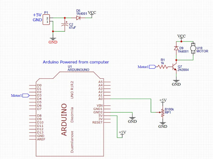
I have the following arduino code that reads potentiometer values and map them to values between 0 255 in order to control small 3.3V mini vibration motors.
const int potPin = A0;
const int motorPin = 3;
const int threshold = 2;

int potValue = 0;
int pwmValue = 0;
int prevPWM = 0;

void setup() {
  pinMode(motorPin, OUTPUT);
  Serial.begin(115200);
}

void loop() {
  potValue = analogRead(potPin);
  pwmValue = map(potValue, 0, 1023, 0, 255);

  if (abs(pwmValue - prevPWM) > threshold) {
    analogWrite(motorPin, pwmValue);
    Serial.print("PWM ");
    Serial.println(pwmValue);
    prevPWM = pwmValue;
  }
}
I try to understand the use of the transistor in the above application. a small current at the transistor gate will open a “way” to larger current to pass from VCC via the motor pins to transistor collector to the emmiter ?
what I should know about the transistor datasheet that is relevant for me?
looking at this 2N3904 datasheet - there is a lot of information in the table - what should I look at?
any other explanation of how the transistor works in that configuration?
The forward voltage of a diode is not a constant, it will vary with current. If you want to power the motor with 5V it's OK just don't expect it to last very long.
In any case you need to reduce the base resistor value. You want to make sure that the transistor is fully on so to speak.
There are different rules of thumb but I usually you the 5X rule. So make sure the collector current is 5X what is needed. Lets say the motor needs 100mA, so the collector current should be at 500mA. With a minimum Hfe of 50 for the 2N3904 the base current should be 500/50 = 10mA.
With 5V from the Arduino and a Vbe of 0.7V, the resistor should be (5-0.7)/10mA = 430 ohms, 470 is close enough
The base resstor of the transistor is 1k. So, base current is about 5-0.7/1000 = 4.3 mA. The following saturation curve (Fig-1) shows that 4.3 mA base current causes VCE(sat) to be around 0.43V. So, @PaulRB's assumption of 0.7V makes some sense!
My 5X rule does not imply that the transistor you are using can handle the 5X current, it is just a simple and easy calculation to make sure that the transistor is in complete saturation and acts like an on/off switch.
Since the 2N3904 has a max Ic of 200mA, it should be adequate for your motor if you power it with 3.3V.
You should read the tutorials that I gave links to.
Best way to learn is to build the circuits and measure the voltages and currents.
It's not a good idea to exceed the manufacturer's specification. It might "handle it", but it might not last long.
As mentioned, in-rush current can be a lot more than the running current.
A good example is a halogen lamp. It might pull 1-Amp when very hot, but 10-Amps when cold.