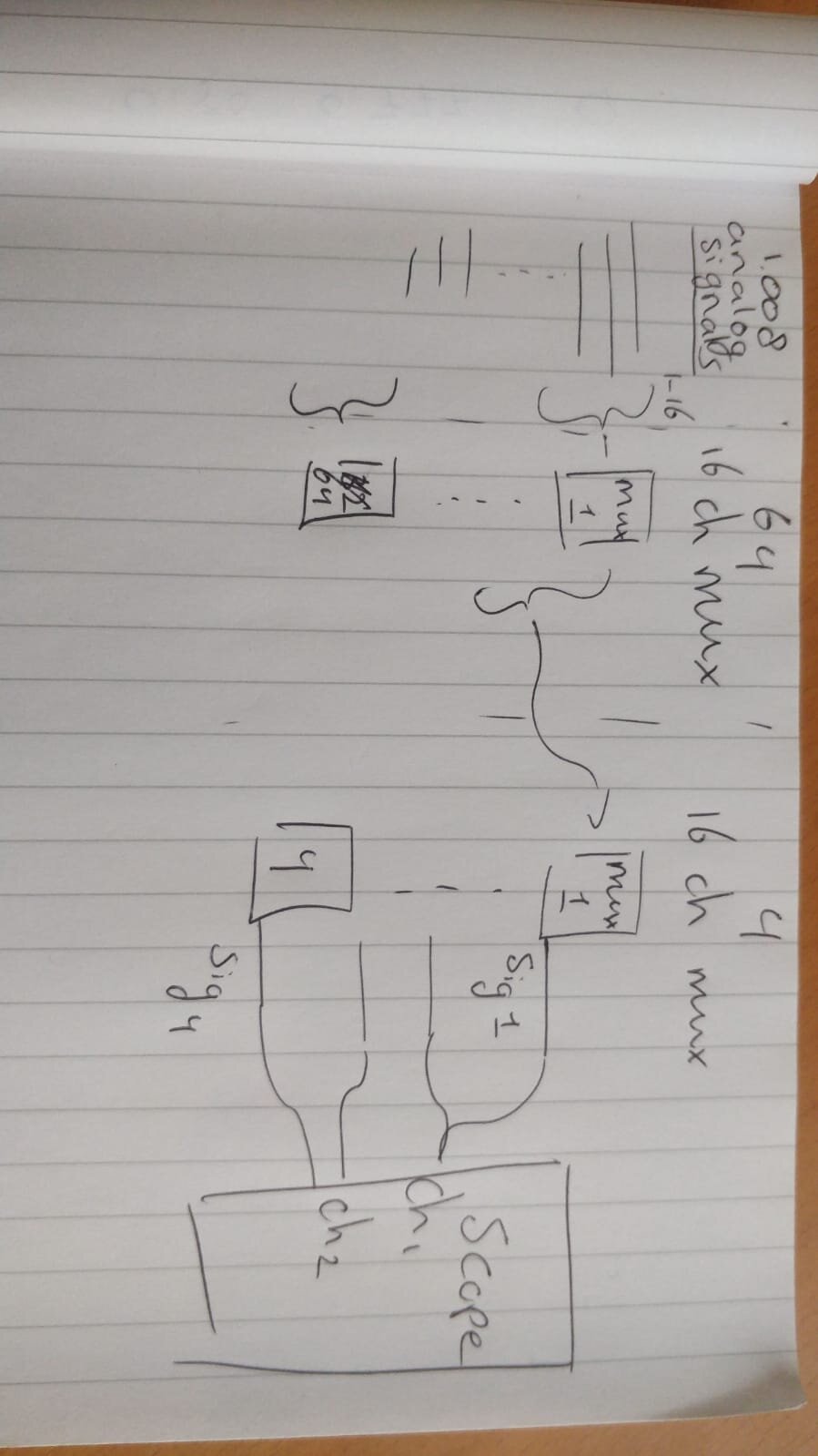
First thank you for reading and hopefully being able to help me out. For a project I want to decrease the amount of analogue signals I have such that I can read the signals on an oscilloscope. To be more clear, I have 1008 analogue signals which I want to reduce to 4. These 4 signals I want to read out on a differential scope (so 2 signals per differential reading) on 2 scope channels.
I want to switch between all 1008 initial signals, such that I switch between these signals on my scope (at about 200 Hz). To do so I want to use 64 16 channel multiplexers, to decrease the initial 1008 signals to 64. Then I want to use a second layer of 16 channel multiplexers to decrease the amount of signals to my final amount of 4.
I'd like to connect all my first 64 Multiplexers to the same (5 logical) Arduino uno digital outputs, in order to save the needed amount of output pins. Then I want to use 5 new pins to control the final 4 Multiplexers.
The problem I am afraid of is that I am not sure if the limited current from a digital output pin will cause this setup to not function properly. I was planning on using the well known CD74HC4067, which states a switching current of 20 mA. Would this mean that would need a current supply of 20 mA*64=1280 mA? Of would this just decrease the make/brake time?
I have attached a simple overview and I look forward to your replies. If anything is unclear feel free to ask for some clarification. Thank you in advance
CD74HC4067, which states a switching current of 20 mA. Would this mean that would need a current supply of 20 mA*64=1280 mA?
No, I think that's the current that can be switched between the multiplexer input/output channels, not the current required to change the selected channel. That current will be very small. However, you will need to switch 64 of them at the same time, and that may be too much for the Arduino pins. Suggest you use some buffer chips such as 74hc06, to buffer each arduino pin and feed the signal to 10 or 12 multiplexer channel select inputs each. The fact that these are inverting buffers is not a concern. You can easilly compensate in your code, if needed.
It would be wise to try the circuit out with just 4 multiplexers, to check that the signal quality arriving at the scope is acceptable.
Why do you say 5 pins to control the multiplexers?
Ah that would make sense.
If I understand the idea behind a buffer chip enough after some Google searches. Would a buffer chip in a sense just translate an Arduino data pin 5V or GND signal to the a 5V or GND signal, but then drawn from a 5V Vcc supply (for example the 5V Arduino supply pin)? Such that the amount of allowed current draw is limited by Vcc and not the digital pin?
Also worthwhile calculating the total current draw of all the multiplexers and buffer chips, to check the power supply you intend to use is sufficient. How do you plan to power the whole circuit? If via usb, that is normally limited to 500mA, and the Uno will require about 50mA of that for itself.
Don't forget you will need a 0.1uF decoupling cap for every chip.
I'm not sure how to determine that exactly? My guess is that (if I'm now using the correct data) 1 MUX would draw about 200 μ when changing the state of S0, S1, S2 and S3 (see figure). However I'm not sure if this would be the right data from the datasheet :o.
Are the buffer chips then still needed you think?
Is there a specific reason a decoupling capacitor is needed? Won't a multiplexer just work without one as well or is a decoupling capacitor just an insurance for proper functioning?
And to respond to your earlier question. I stated five inputs, because I was also counting the enable signal.
Yes, that table is a little difficult to interpret! But stop thinking in terms of current drawn when switching channels. The table is showing "quiescent" current which will be consumed by the chip all the time. If there is a momentary increase in current when switching channels, it is not shown in that table. This is what the bypass capacitors help with. They act as small charge reservoirs which can provide momentary increases in current so that they don't cause momentary voltage changes which could cause problems in the whole circuit.
It might be better to start building a small prototype, as I suggested earlier, perhaps on breadboard, with just 4 multiplexers. You won't need the buffers for that. This will allow you to find out whether these multiplexers are going to be suitable for your project, or if they degrade the signals too much.
If they are ok, you can measure the quiescent current for those 4 and scale that up to estimate what all 68 will require. You can also try adding the buffer chips at this point, to see how much difference they make.
Once you have the simple prototype working, hopefully you will have learned enough and gained confidence to design a pcb. I would suggest 17 multiplexers and a buffer chip per board, making each board into a 256 to 1 multiplexer. 4 identical boards would then allow you to build your final circuit.