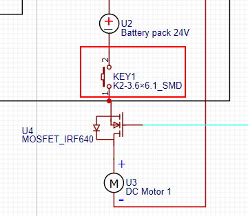
Helloo. So, I was trying to control this motor with an arduino nano and eventually the nano stopped working. I don't really know why and how to proceed. Here is a print of how my circuit looks like. The motor takes up to 5A current based on load. Somebody told me to use an optocoupler but I don't know if it can be fast enough for the pwm to work properly. I would love any advice
Your circuit shows an SMD-button.
Are you sure that this SMD-button can deal with a current of 5A?
To state the obvious: Did you press down the button when testing the circuitry?
The MOS-FET IRF640 has a threshold-voltage up to 4V.
What arduino nano is this 5V or 3.3V?
3.3V will be too less to drive the MOS-FET
5V might still bee too less for 5A
This depends on your PWM-frequency and the type of optocoupler
there are optocoupler that can switch really fast up to the MHz-range
Please correct if needed, the drawing is a big help, thanks for posting it. The MOSFET chosen is a bad choice, I think you probably fried it because it did not turn fully on. It was a good choice as it is Repetitive avalanche rated and your design is good as do not need a flyback diode. The MSOFET diode will conduct at a lower voltage. Did it get hot? What was the heatsink capacity. Get a MOSFET that will turn on around 3.5-3V if your Nano is 5V. You will need a lower Vgs if it a 3.3V Nano. The lower the RDSon the cooler it will run. I would also suggest using resistor maybe 27 ohm in the gate lead.
Your circuit diagram has some serious problems: no gate resistor, and it is missing the essential flyback diode. It seems likely that the high voltages generated by the motor destroyed the Nano.
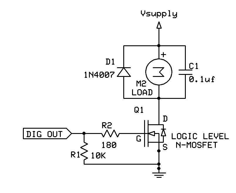
Here is the basic MOSFET motor control circuit. Be sure to use a logic level MOSFET (the IRF640 is NOT a logic level MOSFET).
Thanks for the reply. The mosfet is still working and did not get too hot (not as hot as some other things I fried lol). I've read the datasheet of the mosfet I'm using and I think Vgs tells the threshold, it says 4V max.
I didn't even know these mosfet existed until now. Thanks for the info. But, doesn't it mean it needs to have a voltage the same as the Vsupply in the gate for it to open?
I don't understand what you want to ask with that.
A MOS-FET needs a minimum-voltage to become fully conductant.
threshold voltage means this is the voltage where the MOS-FET starts to become conductant. (current 250 µA = 0,00025 A. Beeing that bit tiny conductant means a still much to high ON-resistance which would make the MOS-FET way too hot.
The switching voltage must be clearly above the threshold-voltage.
5V is above the max of 4V threshold voltage still the values of the IRF640 are not the best for microcontroller-applications.
The IRF3708 is much better suited
lower RD_on = 0,012 Ohm (compared to IRF640 0,18 Ohm
voltage would still be high enough 30V
RDS-on very low already at 3.3V
Thanks for the advices. I'm a totally newb with this stuff.
I just don't think I understand when you say logic level gate control. I'm controlling with pwm, is it the same? And how would I wire it in order for it to activate with the arduino pin? I move the mosfet to control the current of the gate of the logic level mosfet?
logic level means the voltage-level to switch the MOS-FET fully on is below 5V.
Fully on means the RDS-on-resistance dropped down to this 0,x Ohm-value.
5V (or in newer microcontrollers it is only 3.3V) is the voltage-level of "logic-device" = the microcontroller