Controlling an 8x8 RGB LED matrix using SPI

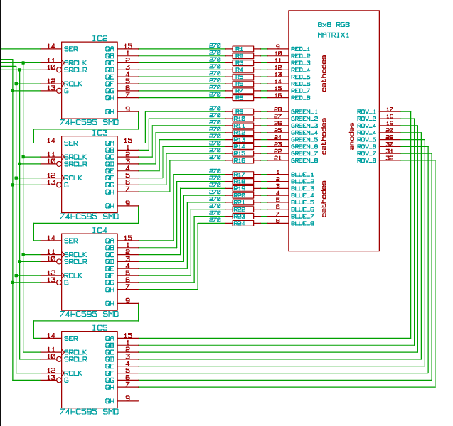
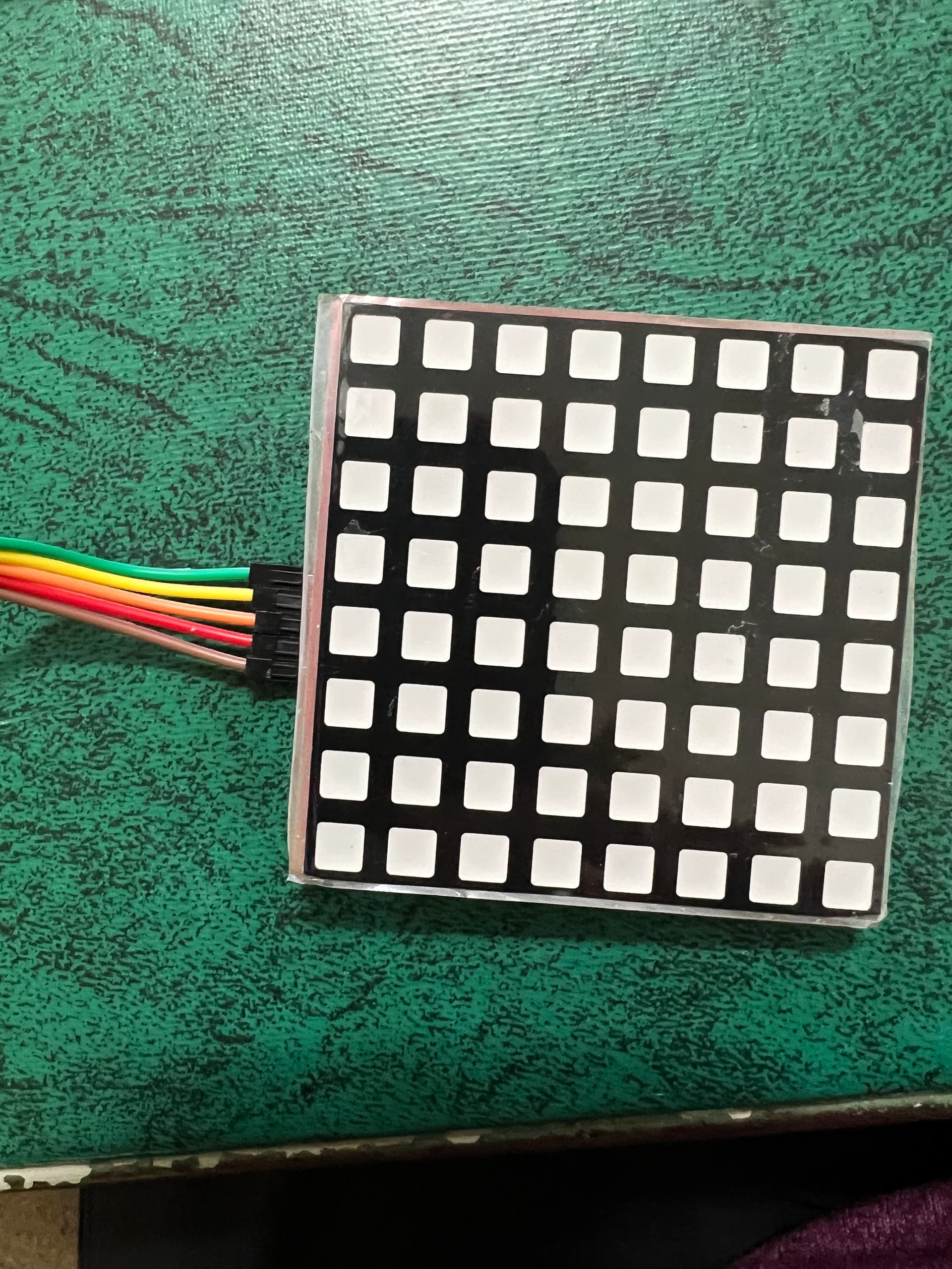
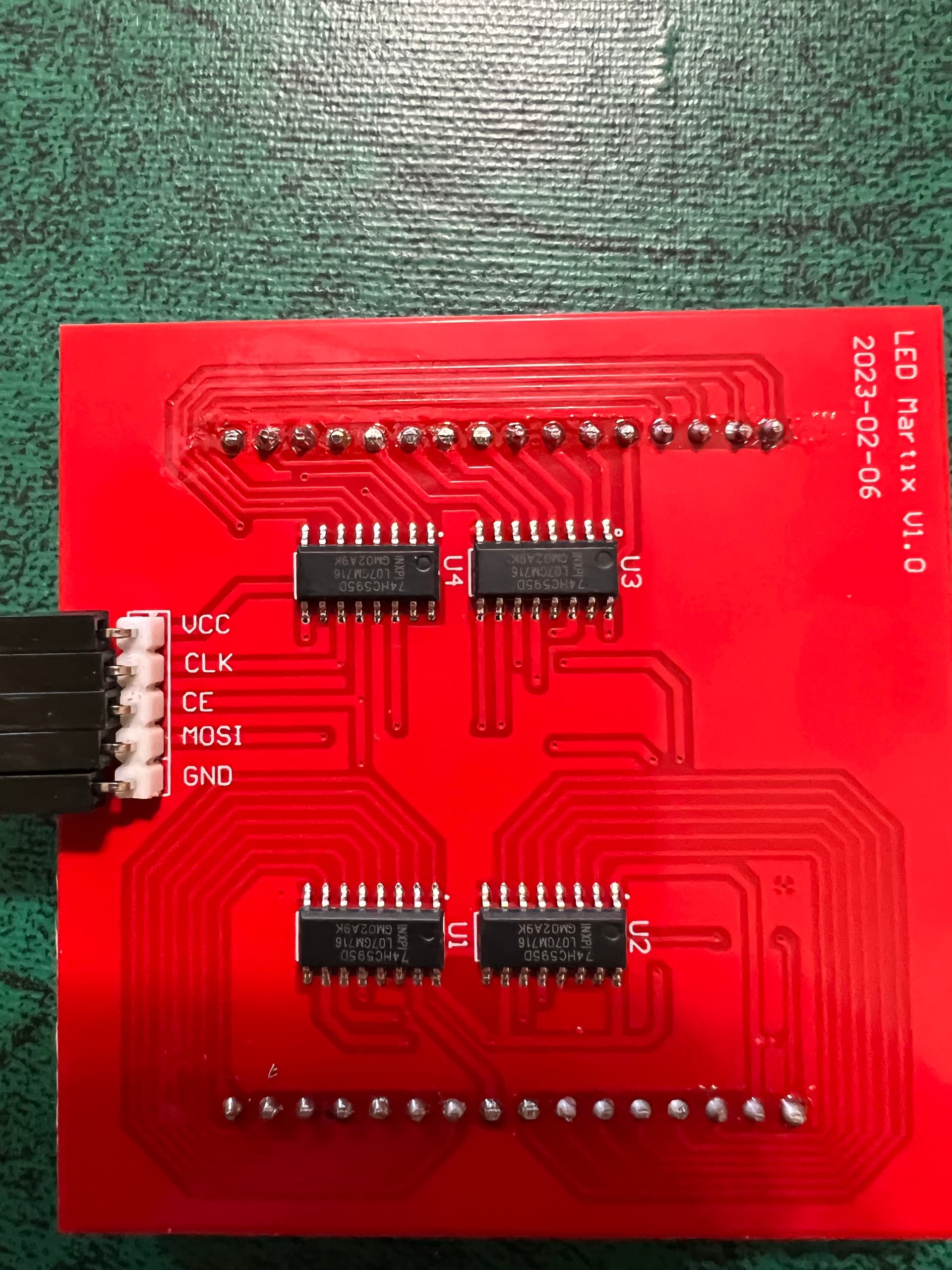
I purchased a Reland Sun 8x8 Full Color RGB LED matrix. It came with no information and I can't find much online about how to mix the colors. It uses SPI protocol and has 5 pins (VCC, GND, SCK, MOSI and CE) which I connected to the appropriate Arduino Uno pins - SCK to 13, MOSI to 11, and CE to 10 and of course the power pins.

I found code that allows me to create a pattern in red, or green or blue only but I want to try to create patterns in other colors.

I was able to figure out how to create some different colors, but not how to make a particular pattern in a different color. For example, I have the code for an arrow, but I can only have it show up in red, green or blue and if I try to make other colors I get random lights. I can show you my code, but is there some library that makes it easier for this type of matrix?'

I've tried several libraries and none of them work with this matrix or at least I can't figure out how to make it work. I want to be able to control each pixel like the neopixel library allows but that doesn't work with this device?

Does anyone have any advice other than "buy a different device?" (which I am willing to do as this only cost me $11)

The code below will display a red heart. When I copy the line ~heart[j]; to another color like data[1] I get really weird things happen. It doesn't mix the colors like I would expect it to.


//Go here to find hex codes for pictures (sprites)  https://gurgleapps.com/tools/matrix#tp-color


#include <SPI.h>                  //  include the head file to enable the  library.

static uint8_t data[4] = {0x00, 0x0, 0x0, 0x0};         // defined a data matrix
static uint8_t i = 1;                                                    // defined a variable vector
const int CE = 10;                                                      // defined  the CE function pin

void heartbig()                                                  // defined a function called "heart big".
{
  int j;                                                                  
  int x = 2;
  static uint8_t heart[8] = {0x00, 0x66, 0xFF, 0xFF, 0xFF, 0x7E, 0x3C, 0x18};    // you need to calculate which led should be light up by this array, it defined line by line on your matrix, for example , 0x00 means the led of the first line is off,  and the 0x66 means the second line's first led will go off and the fourth led will go off and fifth led will go off and eight led will go off. others will turn on....and so on.

  for ( j = 0; j < 8; j++)
  {
    data[0] = ~heart[j];       // color red
    data[2] = 0xFF;             // color blue
    data[1] = 0xFF;             // color green
    data[3] = 0x01 << j ;    // display the data on matrix.
    digitalWrite(CE, LOW);     // when CE is low, it begin to receive data.
    SPI.transfer(data[0]);         //transfer data[0] to the matrix(red)
    SPI.transfer(data[2]);         //transfer data[2] to the matrix(green)
    SPI.transfer(data[1]);        // transfer   data[1] to the matrix(blue)
    SPI.transfer(data[3]);      // tansfer data[3] to the matrix( scanning and display the data on matrix)
    digitalWrite(CE, HIGH);    // when CE is High, means that matrix begin to display the array's information to the matrix.
    delay(x);                          // a little bit delay, let the led light up and stay for a while so that it looks like it brightness.
  }
};


void setup() {
  pinMode(CE, OUTPUT);                          //initialized the pin's mode.
  SPI.begin();                                              // start spi function
}

void loop()                                                  //defined a loop function
{
  int m = 10;
  for ( m = 10; m > 0; m--) {                     // make a for loop to let the data displayed on the matrix.
    heartbig();
  };
  
}
type or paste code here

Can you find a schematic for the PCB behind the matrix?

I see 4x 74hc595 chips. I don't see any bypass capacitor or current limiting resistors. I think this is probably a poor design and would not expect it to have a long life. But it could be fun while it lasts!

It should be possible to mix 7 colours quite easily (red, blue, green, yellow, cyan, magenta, white).

If you want more colours than that, it should be possible, but the code would be beyond beginner level.

So I suggest we help you get those 7 colours, and if you decide you want more and are ready to learn some more advanced coding, the forum will give you all the help you want.

This should give you a yellow heart

//Go here to find hex codes for pictures (sprites)  https://gurgleapps.com/tools/matrix#tp-color


#include <SPI.h>                  //  include the head file to enable the  library.

static uint8_t data[4] = {0x00, 0x0, 0x0, 0x0};         // defined a data matrix
static uint8_t i = 1;                                                    // defined a variable vector
const int CE = 10;                                                      // defined  the CE function pin

void heartbig()                                                  // defined a function called "heart big".
{
  int j;                                                                  
  int x = 2;
  static uint8_t heart[8] = {0x00, 0x66, 0xFF, 0xFF, 0xFF, 0x7E, 0x3C, 0x18};    // you need to calculate which led should be light up by this array, it defined line by line on your matrix, for example , 0x00 means the led of the first line is off,  and the 0x66 means the second line's first led will go off and the fourth led will go off and fifth led will go off and eight led will go off. others will turn on....and so on.

  for ( j = 0; j < 8; j++)
  {
    data[0] = ~heart[j];       // color red
    data[2] = 0xFF;             // color blue
    data[1] = ~heart[j];             // color green
    data[3] = 0x01 << j ;    // display the data on matrix.
    digitalWrite(CE, LOW);     // when CE is low, it begin to receive data.
    SPI.transfer(data[0]);         //transfer data[0] to the matrix(red)
    SPI.transfer(data[2]);         //transfer data[2] to the matrix(green)
    SPI.transfer(data[1]);        // transfer   data[1] to the matrix(blue)
    SPI.transfer(data[3]);      // tansfer data[3] to the matrix( scanning and display the data on matrix)
    digitalWrite(CE, HIGH);    // when CE is High, means that matrix begin to display the array's information to the matrix.
    delay(x);                          // a little bit delay, let the led light up and stay for a while so that it looks like it brightness.
  }
};


void setup() {
  pinMode(CE, OUTPUT);                          //initialized the pin's mode.
  SPI.begin();                                              // start spi function
}

void loop()                                                  //defined a loop function
{
  int m = 10;
  for ( m = 10; m > 0; m--) {                     // make a for loop to let the data displayed on the matrix.
    heartbig();
  };
  
}

Thanks, Paul. That's what I thought and tried, but everything is still red except for the last two pixels on the bottom row which are a bit orange. It is acting kind of strange.

I can't find a schematic but I found this information. This is all I can find about this device.

RPI.pdf (531.6 KB)

As far as I know, the 74HC595 does not communicate with a standard SPI protocol.
They have their own protocol.
In the 74HC595 datasheet, (page 4), you will find a time chart showing how the communication between a processor and a 74HC595 is done.

Apparently your board has the 74HC595 and the RGB LEDs connected as in the diagram below.

HTH

Looking at the PCB, the schematic seems to be a little bit more confused than that. See, one of the four drivers has it's wires all over the place while the other three seem to be connected in a more or less straightforward way.

@efeigenbaum, depending on what you want to do with it, seeing that there are no resistors in the PCB, it might be better to buy a different one indeed. This one wouldn't last very long.

But before I claim that with absolute confidence, could you check something? Are there components between the matrix and the PCB? Could you take a look?

@ruilviana where did you find this? Please post a link.

Interesting. Ok.

What colour does this give?

//Go here to find hex codes for pictures (sprites)  https://gurgleapps.com/tools/matrix#tp-color


#include <SPI.h>                  //  include the head file to enable the  library.

static uint8_t data[4] = {0x00, 0x0, 0x0, 0x0};         // defined a data matrix
static uint8_t i = 1;                                                    // defined a variable vector
const int CE = 10;                                                      // defined  the CE function pin

void heartbig()                                                  // defined a function called "heart big".
{
  int j;                                                                  
  int x = 2;
  static uint8_t heart[8] = {0x00, 0x66, 0xFF, 0xFF, 0xFF, 0x7E, 0x3C, 0x18};    // you need to calculate which led should be light up by this array, it defined line by line on your matrix, for example , 0x00 means the led of the first line is off,  and the 0x66 means the second line's first led will go off and the fourth led will go off and fifth led will go off and eight led will go off. others will turn on....and so on.

  for ( j = 0; j < 8; j++)
  {
    data[0] = 0xFF;       // color red
    data[2] = ~heart[j];             // color blue
    data[1] = ~heart[j];             // color green
    data[3] = 0x01 << j ;    // display the data on matrix.
    digitalWrite(CE, LOW);     // when CE is low, it begin to receive data.
    SPI.transfer(data[0]);         //transfer data[0] to the matrix(red)
    SPI.transfer(data[2]);         //transfer data[2] to the matrix(green)
    SPI.transfer(data[1]);        // transfer   data[1] to the matrix(blue)
    SPI.transfer(data[3]);      // tansfer data[3] to the matrix( scanning and display the data on matrix)
    digitalWrite(CE, HIGH);    // when CE is High, means that matrix begin to display the array's information to the matrix.
    delay(x);                          // a little bit delay, let the led light up and stay for a while so that it looks like it brightness.
  }
};


void setup() {
  pinMode(CE, OUTPUT);                          //initialized the pin's mode.
  SPI.begin();                                              // start spi function
}

void loop()                                                  //defined a loop function
{
  int m = 10;
  for ( m = 10; m > 0; m--) {                     // make a for loop to let the data displayed on the matrix.
    heartbig();
  };
  
}

Good point, there could be resistors, caps, and perhaps even some transistors on the other side of the PCB, below the matrix. I won't get my hopes up too much, though.

If there aren't any resistors, maybe that explains why @efeigenbaum has been unable to mix any colours. The lower forward voltage of the red LEDs, compared to the green & blue, will probably prevent the green & blue LEDs from lighting.

If I'm right, the only way to mix colours will be to alternate red, green and blue on separate scans of the matrix.

Indeed, so the way to mix colors would be to rapidly alternate between the colors. Filling up the capacity of the controller and being a very good second reason to buy another one.

@efeigenbaum what does this code do?

//Go here to find hex codes for pictures (sprites)  https://gurgleapps.com/tools/matrix#tp-color


#include <SPI.h>                  //  include the head file to enable the  library.

static uint8_t data[4] = {0x00, 0x0, 0x0, 0x0};         // defined a data matrix
static uint8_t i = 1;                                                    // defined a variable vector
const int CE = 10;                                                      // defined  the CE function pin

void heartbig()                                                  // defined a function called "heart big".
{
  int j;                                                                  
  int x = 666;
  static uint8_t heart[3][8] = {
    // you need to calculate which led should be light up by this array, it defined line by line on your matrix, for example , 0x00 means the led of the first line is off,  and the 0x66 means the second line's first led will go off and the fourth led will go off and fifth led will go off and eight led will go off. others will turn on....and so on.
    {0x00, 0x66, 0xFF, 0xFF, 0xFF, 0x7E, 0x3C, 0x18}, //red pixels
    {0x0F, 0x0F, 0x0F, 0x0F, 0x0F, 0x0F, 0x0F, 0x0F}, //blue pixels
    {0x00, 0x00, 0x00, 0x00, 0xFF, 0xFF, 0xFF, 0xFF} //green pixels
  }

  for ( byte c = 0; c < 3; c++) { // perform red, blue and then green scans
    for ( j = 0; j < 8; j++)
    {
      data[0] = (c==0 ? ~heart[c][j] : 0xFF);       // color red
      data[2] = (c==1 ? ~heart[c][j] : 0xFF);       // color blue
      data[1] = (c==2 ? ~heart[c][j] : 0xFF);       // color green
      data[3] = 0x01 << j ;    // display the data on matrix.
      digitalWrite(CE, LOW);     // when CE is low, it begin to receive data.
      SPI.transfer(data[0]);         //transfer data[0] to the matrix(red)
      SPI.transfer(data[2]);         //transfer data[2] to the matrix(green)
      SPI.transfer(data[1]);        // transfer   data[1] to the matrix(blue)
      SPI.transfer(data[3]);      // tansfer data[3] to the matrix( scanning and display the data on matrix)
      digitalWrite(CE, HIGH);    // when CE is High, means that matrix begin to display the array's information to the matrix.
      delayMicroseconds(x);                          // a little bit delay, let the led light up and stay for a while so that it looks like it brightness.
    }
  }
};


void setup() {
  pinMode(CE, OUTPUT);                          //initialized the pin's mode.
  SPI.begin();                                              // start spi function
}

void loop()                                                  //defined a loop function
{
  int m = 10;
  for ( m = 10; m > 0; m--) {                     // make a for loop to let the data displayed on the matrix.
    heartbig();
  };
  
}

This code causes the top two rows to be cyan, the middle 3-4 green and the last 2 rows cyan.

https://modwiggler.com/forum/viewtopic.php?t=177974

This code did something very interesting....no heart but lots of static colors. I tried to take a picture of it but it was changing colors within the iPhone's camera. I took a video instead as the colors were changing while looking through the camera's lens. Since I can;t upload a video I will send a static picture of the colors I saw and a link to the video I took. That may shed some light as to what it is doing perhaps.

link to video IMG_7391.MOV - Google Drive

I

As far as anything in between the matrix and the PCB - I see three small bumps on the matrix but can't tell what they are. See the picture.

Sadly, understanding how to use this information to cod the device is beyond my ability to understand...

Looking sideways, it indeed looks like a (slightly buggy) heart.
Now we just need to fix the shifting and it might actually work.

1 Like

By the way, this code gives me stripes blue, teal, green, magenta, blue, teal, green and magenta,

data[0] = 0xee; 
  data[2] = 0x22;
  data[1] = 0x99;
  data[3] = 0xff;   // 0x01 << j ;
  digitalWrite(CE, LOW);
  SPI.transfer(data[0]);
  SPI.transfer(data[2]);
  SPI.transfer(data[1]);
  SPI.transfer(data[3]);
  digitalWrite(CE, HIGH);
  delay(2);

@ruilviana I don't think we can be certain that schematic belongs to @efeigenbaum 's board. Seems like the guy asking questions in that forum was designing something similar, but from scratch. Later he was asking about adding transistors to increase the brightness, which would not be an option if he was using the same board @efeigenbaum has.

1 Like

The heart is there. This is exactly how I hoped it would look, to demonstrate the 7 basic colours. The heart is overlaid on 4 squares of other colours. The heart is red and the squares are black, blue, green and cyan (what you called teal). Where the red heart overlaps those other colours, you can see magenta, yellow and white.

The movement you can see on the video is probably caused by the difference in the frame rate of the camera compared to the refresh rate of the matrix.