The other components we were hoping to see would be on the back side of the PCB, not inside the moulding of the matrix. I don't see any components on the back of the PCB. I don't know what those bumps in the matrix are, but I don't think they are anything important.
Try this and post a picture
  data[0] = 0b01010101;
  data[2] = 0b00110011;
  data[1] = 0b00001111;
Here's what it did. I think I see what you are doing - I am assuming you expected the 4th column to be magenta, the 7th teal and the last white? It seems that red is a bit overpowering perhaps...?

Oh I see the heart now - I was looking at it sideways.
Yes, that's exactly the problem.
If you remember, I said
Looks like it doesn't completely prevent them from lighting, but it certainly has a dominating effect.
So my solution is the correct one, I think:
Unfortunately this will reduce the brightness of all colours, but at least they can be mixed equally.
Interesting....so how do I do this?
That is what the code I put in post #11 does.
Try this
//Go here to find hex codes for pictures (sprites)  https://gurgleapps.com/tools/matrix#tp-color


#include <SPI.h>                  //  include the head file to enable the  library.

static uint8_t data[4] = {0x00, 0x0, 0x0, 0x0};         // defined a data matrix
static uint8_t i = 1;                                                    // defined a variable vector
const int CE = 10;                                                      // defined  the CE function pin

void heartbig()                                                  // defined a function called "heart big".
{
  int j;
  int x = 666;
  static uint8_t heart[3][8] = {
    // you need to calculate which led should be light up by this array, it defined line by line on your matrix, for example , 0x00 means the led of the first line is off,  and the 0x66 means the second line's first led will go off and the fourth led will go off and fifth led will go off and eight led will go off. others will turn on....and so on.
    {0b01010101, 0b01010101, 0b01010101, 0b01010101, 0b01010101, 0b01010101, 0b01010101, 0b01010101}, //red pixels
    {0b00110011, 0b00110011, 0b00110011, 0b00110011, 0b00110011, 0b00110011, 0b00110011, 0b00110011}, //blue pixels
    {0b00001111, 0b00001111, 0b00001111, 0b00001111, 0b00001111, 0b00001111, 0b00001111, 0b00001111} //green pixels
  }

  for ( byte c = 0; c < 3; c++) { // perform red, blue and then green scans
    for ( j = 0; j < 8; j++)
    {
      data[0] = (c==0 ? ~heart[c][j] : 0xFF);       // color red
      data[2] = (c==1 ? ~heart[c][j] : 0xFF);       // color blue
      data[1] = (c==2 ? ~heart[c][j] : 0xFF);       // color green
      data[3] = 0x01 << j ;    // display the data on matrix.
      digitalWrite(CE, LOW);     // when CE is low, it begin to receive data.
      SPI.transfer(data[0]);         //transfer data[0] to the matrix(red)
      SPI.transfer(data[2]);         //transfer data[2] to the matrix(green)
      SPI.transfer(data[1]);        // transfer   data[1] to the matrix(blue)
      SPI.transfer(data[3]);      // tansfer data[3] to the matrix( scanning and display the data on matrix)
      digitalWrite(CE, HIGH);    // when CE is High, means that matrix begin to display the array's information to the matrix.
      delayMicroseconds(x);                          // a little bit delay, let the led light up and stay for a while so that it looks like it brightness.
    }
  }
};


void setup() {
  pinMode(CE, OUTPUT);                          //initialized the pin's mode.
  SPI.begin();                                              // start spi function
}

void loop()                                                  //defined a loop function
{
  int m = 10;
  for ( m = 10; m > 0; m--) {                     // make a for loop to let the data displayed on the matrix.
    heartbig();
  };

}
Take a photo and compare it to the photo in post #23.
Ok, that's why I said:
"Apparently your board has the 74HC595 and the RGB LEDs connected as in the diagram below." ![]()
1 Like
So this is much better and correct I think.
It is reversed, however, with 0(red) 0(blue) and 0(green) being white while before it was off.
But I am getting cyan, magenta, yellow and white.
So, then, how do we get the heart to be displayed in, say, magenta?

1 Like
If this comes out cyan rather than magenta, I'm sure you can figure out what I got wrong...
//Go here to find hex codes for pictures (sprites)  https://gurgleapps.com/tools/matrix#tp-color


#include <SPI.h>                  //  include the head file to enable the  library.

static uint8_t data[4] = {0x00, 0x0, 0x0, 0x0};         // defined a data matrix
static uint8_t i = 1;                                                    // defined a variable vector
const int CE = 10;                                                      // defined  the CE function pin

void heartbig()                                                  // defined a function called "heart big".
{
  int j;
  int x = 666;
  static uint8_t heart[3][8] = {
    // you need to calculate which led should be light up by this array, it defined line by line on your matrix, for example , 0x00 means the led of the first line is off,  and the 0x66 means the second line's first led will go off and the fourth led will go off and fifth led will go off and eight led will go off. others will turn on....and so on.
    {0x00, 0x66, 0xFF, 0xFF, 0xFF, 0x7E, 0x3C, 0x18}, //red pixels
    {0x00, 0x66, 0xFF, 0xFF, 0xFF, 0x7E, 0x3C, 0x18}, //blue pixels
    {0xFF, 0xFF, 0xFF, 0xFF, 0xFF, 0xFF, 0xFF, 0xFF} //green pixels
  }

  for ( byte c = 0; c < 3; c++) { // perform red, blue and then green scans
    for ( j = 0; j < 8; j++)
    {
      data[0] = (c==0 ? ~heart[c][j] : 0xFF);       // color red
      data[2] = (c==1 ? ~heart[c][j] : 0xFF);       // color blue
      data[1] = (c==2 ? ~heart[c][j] : 0xFF);       // color green
      data[3] = 0x01 << j ;    // display the data on matrix.
      digitalWrite(CE, LOW);     // when CE is low, it begin to receive data.
      SPI.transfer(data[0]);         //transfer data[0] to the matrix(red)
      SPI.transfer(data[2]);         //transfer data[2] to the matrix(green)
      SPI.transfer(data[1]);        // transfer   data[1] to the matrix(blue)
      SPI.transfer(data[3]);      // tansfer data[3] to the matrix( scanning and display the data on matrix)
      digitalWrite(CE, HIGH);    // when CE is High, means that matrix begin to display the array's information to the matrix.
      delayMicroseconds(x);                          // a little bit delay, let the led light up and stay for a while so that it looks like it brightness.
    }
  }
};


void setup() {
  pinMode(CE, OUTPUT);                          //initialized the pin's mode.
  SPI.begin();                                              // start spi function
}

void loop()                                                  //defined a loop function
{
  int m = 10;
  for ( m = 10; m > 0; m--) {                     // make a for loop to let the data displayed on the matrix.
    heartbig();
  };

}
Well...I hate to be a pain, but.unfortunately, this is what I got.
I do appreciate how much you've been helping me. I guess I just understand what its doing and how the other code (0b0101010....etc) is related since we are not using it here.
But then I switched it to this:
static uint8_t heart[3][8] = {
// you need to calculate which led should be light up by this array, it defined line by line on your matrix, for example , 0x00 means the led of the first line is off, and the 0x66 means the second line's first led will go off and the fourth led will go off and fifth led will go off and eight led will go off. others will turn on....and so on.
{0x00, 0x66, 0xFF, 0xFF, 0xFF, 0x7E, 0x3C, 0x18}, //red pixels
    {0x00, 0x66, 0xFF, 0xFF, 0xFF, 0x7E, 0x3C, 0x18}, //blue pixels
    {0x00, 0x00, 0x00, 0x00, 0x00, 0x00, 0x00, 0x00} //green pixels
  };
and got the following: It is actually the right color - just looks wrong in the picture
Yay!!!!!
Thanks so much!!! I think I know how to do it for other pictures now,
2 Likes
Well done, you spotted my error! I mistakenly turned on all the green LEDs, making the background green and the heart white.
So what next? Are you happy with these 7 colours or do you want more?
If you think you know how to get other colors, we can try it. How difficult do you think it would be?
Not too difficult, I think. We can keep it as simple as possible and try for 31 colours.
//Go here to find hex codes for pictures (sprites)  https://gurgleapps.com/tools/matrix#tp-color


#include <SPI.h>                  //  include the head file to enable the  library.

static uint8_t data[4] = {0x00, 0x0, 0x0, 0x0};         // defined a data matrix
static uint8_t i = 1;                                                    // defined a variable vector
const int CE = 10;                                                      // defined  the CE function pin

void heartbig()                                                  // defined a function called "heart big".
{
  int j;
  int x = 444;
  static uint8_t heart[2][3][8] = {
    // you need to calculate which led should be light up by this array, it defined line by line on your matrix, for example , 0x00 means the led of the first line is off,  and the 0x66 means the second line's first led will go off and the fourth led will go off and fifth led will go off and eight led will go off. others will turn on....and so on.
    {
      {0b01010101, 0b01010101, 0b01010101, 0b01010101, 0b00000000, 0b00000000, 0b00000000, 0b00000000}, //red pixels
      {0b00110011, 0b00110011, 0b00110011, 0b00110011, 0b00000000, 0b00000000, 0b00000000, 0b00000000}, //blue pixels
      {0b00001111, 0b00001111, 0b00001111, 0b00001111, 0b00000000, 0b00000000, 0b00000000, 0b00000000} //green pixels
    },
    {
      {0b01010101, 0b01010101, 0b00000000, 0b00000000, 0b01010101, 0b01010101, 0b00000000, 0b00000000}, //red pixels
      {0b00110011, 0b00110011, 0b00000000, 0b00000000, 0b00110011, 0b00110011, 0b00000000, 0b00000000}, //blue pixels
      {0b00001111, 0b00001111, 0b00000000, 0b00000000, 0b00001111, 0b00001111, 0b00000000, 0b00000000} //green pixels
    }
  }

  for ( byte b = 0; b < 2; b++) { // perform bright scan then dimmer scan
    for ( byte c = 0; c < 3; c++) { // perform red, blue and then green scans
      for ( j = 0; j < 8; j++)
      {
        data[0] = (c==0 ? ~heart[b][c][j] : 0xFF);       // color red
        data[2] = (c==1 ? ~heart[b][c][j] : 0xFF);       // color blue
        data[1] = (c==2 ? ~heart[b][c][j] : 0xFF);       // color green
        data[3] = 0x01 << j ;    // display the data on matrix.
        digitalWrite(CE, LOW);     // when CE is low, it begin to receive data.
        SPI.transfer(data[0]);         //transfer data[0] to the matrix(red)
        SPI.transfer(data[2]);         //transfer data[2] to the matrix(green)
        SPI.transfer(data[1]);        // transfer   data[1] to the matrix(blue)
        SPI.transfer(data[3]);      // tansfer data[3] to the matrix( scanning and display the data on matrix)
        digitalWrite(CE, HIGH);    // when CE is High, means that matrix begin to display the array's information to the matrix.
        delayMicroseconds(x);                          // a little bit delay, let the led light up and stay for a while so that it looks like it brightness.
      }
    }
    x = x >> 1; // reduce the time by half for the dimmer scan
  }
};


void setup() {
  pinMode(CE, OUTPUT);                          //initialized the pin's mode.
  SPI.begin();                                              // start spi function
}

void loop()                                                  //defined a loop function
{
  int m = 10;
  for ( m = 10; m > 0; m--) {                     // make a for loop to let the data displayed on the matrix.
    heartbig();
  };

}
The above won't display all 31 possible colours, only the basic 7 but with 3 levels of brightness. Let's see what this does, in the meantime I'll try to think how to display all 31 colours on the matrix at the same time.
I hope I got this right, it's not easy coding on a smartphone!
//Go here to find hex codes for pictures (sprites)  https://gurgleapps.com/tools/matrix#tp-color


#include <SPI.h>                  //  include the head file to enable the  library.

static uint8_t data[4] = {0x00, 0x0, 0x0, 0x0};         // defined a data matrix
static uint8_t i = 1;                                                    // defined a variable vector
const int CE = 10;                                                      // defined  the CE function pin

static uint8_t heart[2][3][8];

void heartbig()                                                  // defined a function called "heart big".
{
  int j;
  int x = 444;

  for ( byte b = 0; b < 2; b++) { // perform bright scan then dimmer scan
    for ( byte c = 0; c < 3; c++) { // perform red, blue and then green scans
      for ( j = 0; j < 8; j++)
      {
        data[0] = (c==0 ? ~heart[b][c][j] : 0xFF);       // color red
        data[2] = (c==1 ? ~heart[b][c][j] : 0xFF);       // color blue
        data[1] = (c==2 ? ~heart[b][c][j] : 0xFF);       // color green
        data[3] = 0x01 << j ;    // display the data on matrix.
        digitalWrite(CE, LOW);     // when CE is low, it begin to receive data.
        SPI.transfer(data[0]);         //transfer data[0] to the matrix(red)
        SPI.transfer(data[2]);         //transfer data[2] to the matrix(green)
        SPI.transfer(data[1]);        // transfer   data[1] to the matrix(blue)
        SPI.transfer(data[3]);      // tansfer data[3] to the matrix( scanning and display the data on matrix)
        digitalWrite(CE, HIGH);    // when CE is High, means that matrix begin to display the array's information to the matrix.
        delayMicroseconds(x);                          // a little bit delay, let the led light up and stay for a while so that it looks like it brightness.
      }
    }
    x = x >> 1; // reduce the time by half for the dimmer scan
  }
};

void setPixel(byte row, byte col, byte colour) {
  for (byte c=0; c<3; c++) {
    for (byte b=0; b<2; b++) {
      byte bitPos = c+c+b;
      byte bit = bitRead(colour, bitPos);
      bitWrite(heart[b][c][row], col, bit);
    }
  }
}

void setup() {
  pinMode(CE, OUTPUT);                          //initialized the pin's mode.
  SPI.begin();                                              // start spi function

  //Set up the data to display 31 different colours
  for (byte colour=0; colour<32; colour++) {
    byte row = colour / 8;
    byte col = colour % 8;
    setPixel(row, col, colour);
    setPixel(row+4, col, colour);
  }
}

void loop()                                                  //defined a loop function
{
  int m = 10;
  for ( m = 10; m > 0; m--) {                     // make a for loop to let the data displayed on the matrix.
    heartbig();
  };

}
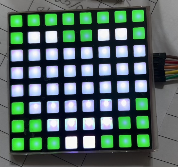
Ok, so I got the following:
white, cyan, yellow, green, magenta, blue, red, off
The last two rows were off.
It is hard to photograph as the colors keep changing on my iPad Camera (better than my phone) and I had to get in pretty close to see the colors.

I can't believe you are doing this on a smartphone!
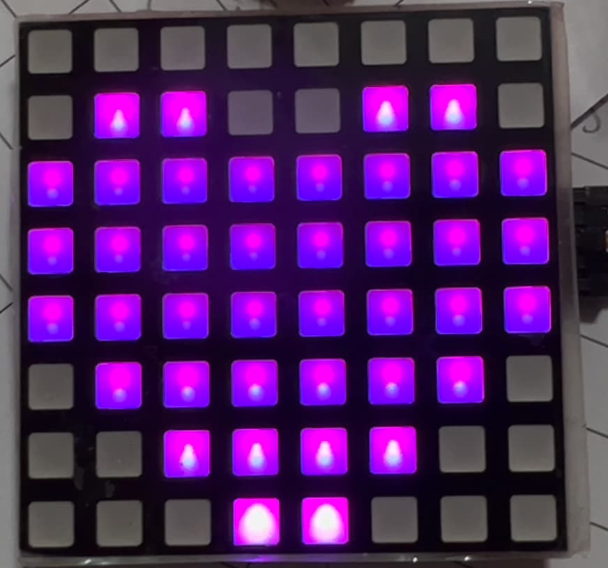
This one is very interesting. No heart but lots of pretty colors. Really hard to get a picture of it accurately. I can try with a real camera instead of a smart device.
this is the most accurate picture I could get - although some of the "whites" are actually pale pink, purple or blue.

Doesn't look too bad...
There is no heart shape, just a test pattern to show all the 31 colours (+black). The bottom half of the matrix is just a repeat of the top half.
Lots of the colours look very similar in the photo. Do all 31 look slightly different to each other in your view, or do some look like duplicates?
Wait a minute, I did make an error. There should be 63 colours, not 31!
How does this look?
//Go here to find hex codes for pictures (sprites)  https://gurgleapps.com/tools/matrix#tp-color


#include <SPI.h>                  //  include the head file to enable the  library.

static uint8_t data[4] = {0x00, 0x0, 0x0, 0x0};         // defined a data matrix
static uint8_t i = 1;                                                    // defined a variable vector
const int CE = 10;                                                      // defined  the CE function pin

static uint8_t heart[2][3][8];

void heartbig()                                                  // defined a function called "heart big".
{
  int j;
  int x = 444;

  for ( byte b = 0; b < 2; b++) { // perform bright scan then dimmer scan
    for ( byte c = 0; c < 3; c++) { // perform red, blue and then green scans
      for ( j = 0; j < 8; j++)
      {
        data[0] = (c==0 ? ~heart[b][c][j] : 0xFF);       // color red
        data[2] = (c==1 ? ~heart[b][c][j] : 0xFF);       // color blue
        data[1] = (c==2 ? ~heart[b][c][j] : 0xFF);       // color green
        data[3] = 0x01 << j ;    // display the data on matrix.
        digitalWrite(CE, LOW);     // when CE is low, it begin to receive data.
        SPI.transfer(data[0]);         //transfer data[0] to the matrix(red)
        SPI.transfer(data[2]);         //transfer data[2] to the matrix(green)
        SPI.transfer(data[1]);        // transfer   data[1] to the matrix(blue)
        SPI.transfer(data[3]);      // tansfer data[3] to the matrix( scanning and display the data on matrix)
        digitalWrite(CE, HIGH);    // when CE is High, means that matrix begin to display the array's information to the matrix.
        delayMicroseconds(x);                          // a little bit delay, let the led light up and stay for a while so that it looks like it brightness.
      }
    }
    x = x >> 1; // reduce the time by half for the dimmer scan
  }
};

void setPixel(byte row, byte col, byte colour) {
  for (byte c=0; c<3; c++) {
    for (byte b=0; b<2; b++) {
      byte bitPos = c+c+b;
      byte bit = bitRead(colour, bitPos);
      bitWrite(heart[b][c][row], col, bit);
    }
  }
}

void setup() {
  pinMode(CE, OUTPUT);                          //initialized the pin's mode.
  SPI.begin();                                              // start spi function

  //Set up the data to display 63 different colours
  for (byte colour=0; colour<64; colour++) {
    byte row = colour / 8;
    byte col = colour % 8;
    setPixel(row, col, colour);
  }
}

void loop()                                                  //defined a loop function
{
  int m = 10;
  for ( m = 10; m > 0; m--) {                     // make a for loop to let the data displayed on the matrix.
    heartbig();
  };

}
You really need something like a DSLR so you can control the shutter speed.
The matrix should in theory be refreshing around 60 times per second, maybe a little less. So you really want a shutter speed at least 10 times longer, so around 1/6 seconds.
Next you will need to adjust the aperture so that the brighter colours don't saturate the camera's sensor. Some DSLR have a preview mode where the screen will indicate any areas of the image that are saturated. Keep reducing the aperture until there are no saturated areas. You might have to reduce the ISO setting also.
1 Like