High Power Dual MOS Tube Transistor MOSFET Trigger Switch Driver Module Adjustable PWM Regulator Switch Control DC 5V-36V 400W
12v 7ah battery
Arduino uno r3 brain
24v DC brushed motor
flyback diode 24v 15ah
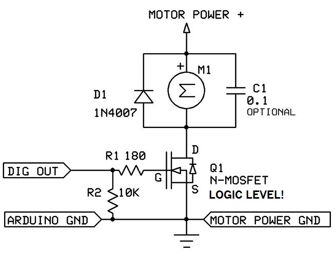
My problem is that the motor will spin no matter what. I've replaced the mosfet and redone all of the wiring but nothing has worked so far.
This is my code that I am trying to use
void setup() {
  // Set the digital pin as an output for Motor 1
  pinMode(5, OUTPUT);
  Serial.begin(9600); //Starts communication with Serial Monitor
}
void loop() {
  digitalWrite(5, LOW); //Starts with the motor off
  Serial.println("Motors OFF for 20 seconds");
  delay(20000); //Waits 20 seconds

  digitalWrite(5, HIGH); //Turns on the motor
  Serial.println("Motors ON for 20 seconds");
  delay(20000); //Waits 20 seconds

}
Please follow the advice given in the link below when posting code, in particular the section entitled 'Posting code and common code problems'
Use code tags (the < CODE/ > icon above the compose window) to make it easier to read and copy for examination
Please post your full sketch, using code tags when you do
Posting your code using code tags prevents parts of it being interpreted as HTML coding and makes it easier to copy for examination
In my experience the easiest way to tidy up the code and add the code tags is as follows
Start by tidying up your code by using Tools/Auto Format in the IDE to make it easier to read. Then use Edit/Copy for Forum and paste what was copied in a new reply. Code tags will have been added to the code to make it easy to read in the forum thus making it easier to provide help.
There's nothing obviously wrong with the wiring or with the sketch. There's an LED on the MOSFET board. Is it ON or OFF ?
If it's ON, the problem comes from the Arduino (how is it powered, you didn't mention)
If it's OFF, the problem comes from the 24V part (Bat -> MOSFET), make sure the connections are as they should and post a close-up view of them.
EDIT: A close-up view shows you invertedinput and output on the MOSFET board!!!
Sorry, after double check, I'm wrong. Be aware that some pictures on the net are misleading. There are markings on the board itself anyway.
While following the code the led turns on for 20 seconds then it turns off for 20 seconds but the motor only stays on for the entire time.
The Arduino is powered via USB to my computer.
The board is rated 3.3V - 20V. 24V is out of that range. Do you have a 20V or less to try
Sorry I'm wrong again, power stage is up to 36V. Mystery remains...