Hi,
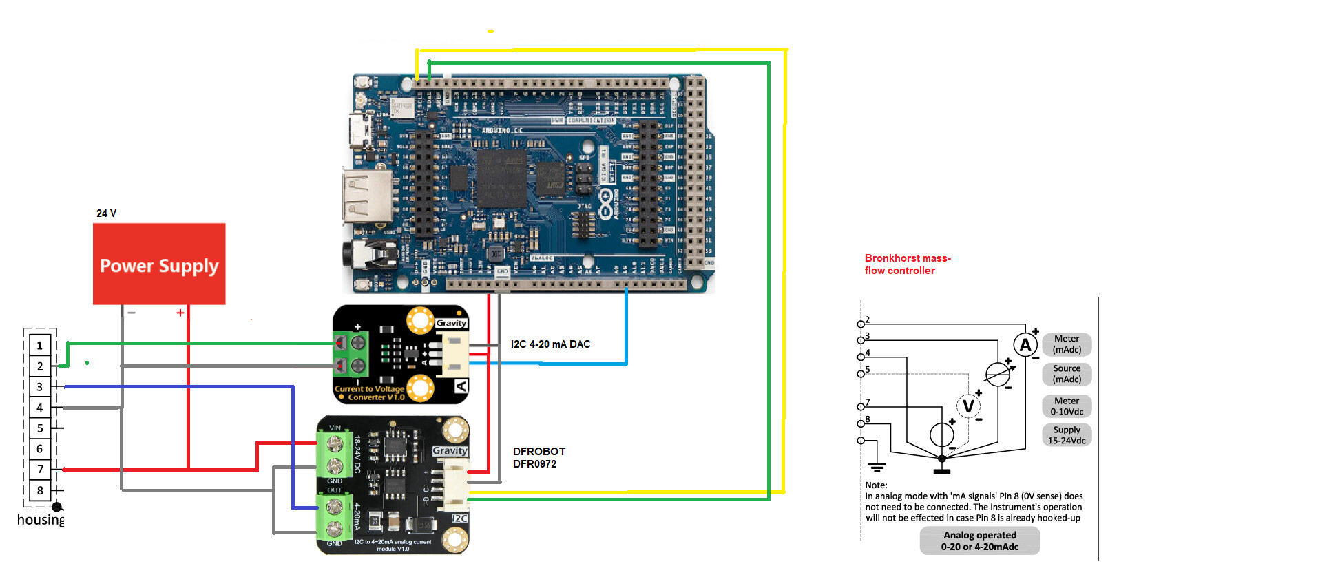
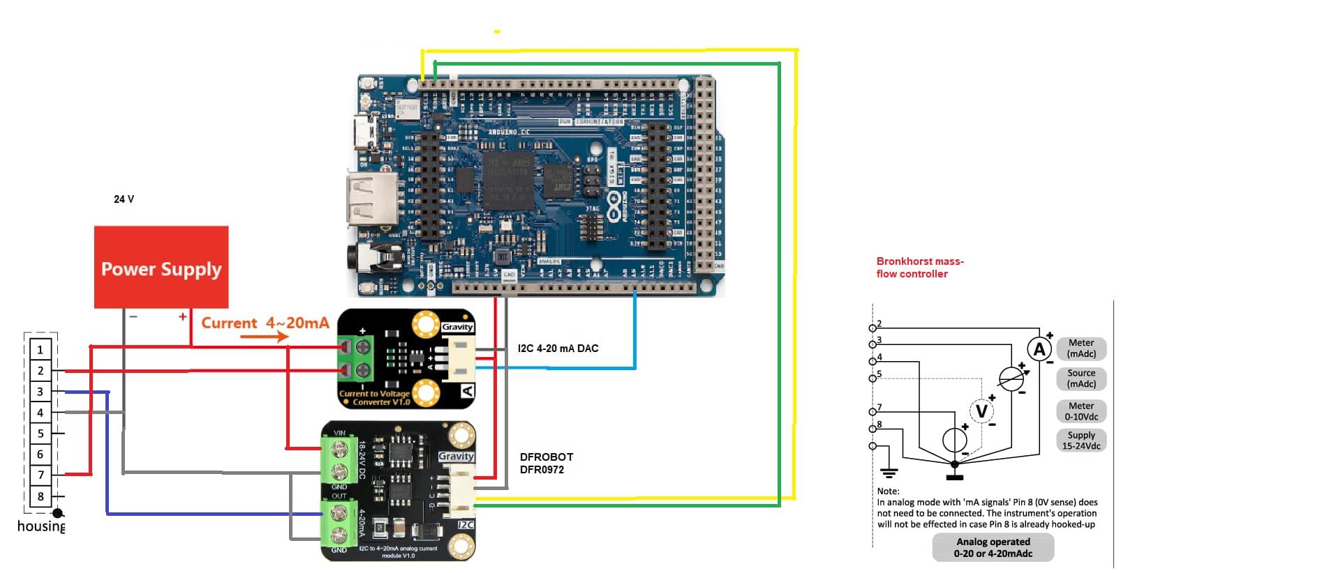
I am trying to control a massflowcontroller with the arduino Giga, see picture . The input signal is very unstable.
Does anyone has ideas whats wrong?
Thanks in advance,
Friedrich
Hi,
I am trying to control a massflowcontroller with the arduino Giga, see picture . The input signal is very unstable.
Does anyone has ideas whats wrong?
Thanks in advance,
Friedrich
Nice picture but not much help in solving your problem there is a lot of information missing. Also consider many of us do not have those parts and probably do not know what they are. A well annotated schematic would help us help you. Links to technical information on the hardware items are needed.
What is the input signal and how is it unstable?
The 4-20 mA output signal from the MFC is very unstable.
Did you confirm that statement with an oscilloscope?
See post 2
Hi Paul,
Yes.
Can you give us a little more detail by what you mean by unstable.
Is it within the sensor noise spec or maybe due to a poor power supply?
Control stability < ± 0,1 % FS
Hi Jim,
The power supply has 24V and 4A.
The signal has a variation of some mA’s
Best regards,
Friedrich
Is the set point current nice and stable?
The setpoint is stable.
Can you give some numbers on the variation, such as the percent of variation, so it can be compared to the product of all the percent of error of all the devices that are involved?
Hi Paul,
I can not test it at home, but the variation is 25% and higher.
Best Regards,
Friedrich
Back at your drawing, the mass flow controller pin connections show pin #8 is the common ground/return connection, but your housing connections show NO CONNECTION to pin # 8.
Hi Paul,
In the note it says pin 8 does not need to be connected
What is powering the Arduino? The diagrams do not show. Is the power supply ground connected to the Arduino ground?
And that can be correct is you DO NOT have another ground connection, which you have in your Arduino side. That creates a ground loop because all the other devices in the controller use the same ground, so their varying currents go through the same circuit as your 20 ma loop current.
The mass-flow controller must have an internal connection between the current loop circuit ground and the enclosure ground. Remove that connection and use the current loop return for the 20ma data. Use the pin 8 for the all the other stuff.
Your symptoms are the clue to the current loop having two grounds!
The 24V power supply is also powering the Arduino.
Exactly how did you measure current with a scope?
Hello technomation,
so you control the flow rate by using analog mode - applying voltage to control and applying current to read flow right?