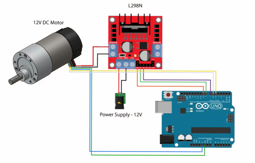
I don't know much about PID algorithm and I would appreciate if anyone can please provide me with some code that will allow me to set an RPM speed as a variable. I haven't had much luck finding anything online. usually they will set the target speed as float vt = 100 * (sin(currT / 1e6) > 0); and I don't understand what this means. I just want it in units of rpm.
Waiting for more concrete replies do some digging about PID, how it works, how it can be tuned in.
There's no code perfect for every application.
P stands for Proportional. Measuring a pot, a sensor kP * "measured value" is the basic factor.
D stands for the derivate, used to speed up a change to receive the target faster. Too much of kD and the target is overshot, might get into oscillation.
I stands for integrate and it sums up the remaining error between wanted value and actual value, adding a final correction to the power given out.
Its a way of saying the needlessly complicated "run at 100 RPM for Pi seconds, then 0 for Pi seconds, repeat forever"
The important part is being able to convert encoder ticks per unit time into RPM, or the inverse which is much more useful for control: convert RPM into encoder ticks per unit time (or RPM into time between encoder ticks). Then your control system could measure the encoder ticks in a period of time, or the time between ticks, figure out if it is too high or too low, and adjust the output accordingly.
Encoders convert revolutions into a number of pulses, and if your device has a pulses-per-revolution number, it would be important so you can write stuff like:
Converting between the units the human wants (RPM) and the units that the hardware works in (encoder counts, microseconds, PWM duty cycles in 0-255, etc,) is important.
Choices you need to make are:
How many RPM are you talking about?
How do you/the user/the program choose RPM?
How are you going to read RPM from the encoder?
How fast are you going to update the PWM to the motor?
One of the first things I'd try is adding a potentiometer and manually controlling the PWM with it, using something like the https://docs.arduino.cc/built-in-examples/analog/AnalogInput/ example. That proves some basic functionality and gives you a test-bed on which to build encoder reading and PID/automatic control.
Once you've got all the power and wiring issues worked out for manual control, then I'd work on using the encoder to read the speed and convert it into RPM.
Once you can set the PWM manually and reliably read the resultant speed, then adding in an automatic control like PID to take over setting the motor's PWM.
I've got a simulation sketch in Wokwi that numerically simulates motor physics and PID control, https://wokwi.com/projects/323970337959051859 which doesn't serve your needs, but can demonstrate some of the problems of the motor dynamics interacting with the control system. If your automated control isn't well matched to the dynamics of your motor, and adjusts too fast or measures too slow, etc, it can easily get out of control.
At first I was worried that your control loop would have problems if the motor was spinning at more than 1 count/ms:
...but then the update speed is limited by all the Serial.printing() at 9600 baud. Starting from a stopped motor, dt will be greater than 0ms.
Good luck!
Edit: Oops. "count" isnt the "EncoderCount", instead "count" is the number of TIMER1_COMPA_vect interrupts in WGMmode 4: CTC top=OCR1A mode ticks. It is configured for 5ms/tick.
This part says "If it running time is greater than 100 seconds, set the RPM to zero." He's using it to shut the motor off after a while.
I think there's an error in here:
where he uses 900. For the 900PPR encoder attached to a " Encoder Metal Gearmotor 12V DC 80 RPM Gear Motor with Encoder for Arduino and 3D Printers" (as found on Amazon) it would be correct if he was reading the encoder only on one edge of one of the encoder signals, but since he's counting the rising and falling edges of both encoder signals, it has twice the specified resolution and needs a divisor of 900PPR * 4count/pulse= 3600counts/rev to get the speeds right.
Yes I watched that, but I found that he lacked a proper explanation on controlling speed. But it did have a lot of great info on PID. Just didn't explain the sinusoidal speed variable so I was confused
I modified the code. I would appreciate if you could please check if it would work (I have been stuck on this for a few days, I don't know where I would be without your help, so thanks)
I am using this motor: Motor
This is the code. The desired RPM is set as a global variable at the top where variables are defined:
// GeeKee CeeBee

// ************ DEFINITIONS************
// PID controller constants
float kp = 0.02;        // Proportional constant
float ki = 0.00015;     // Integral constant
float kd = 0;           // Derivative constant (not used)

// Time variables
unsigned long t;        // Current time
unsigned long t_prev = 0; // Previous time

// Encoder and motor control pins
const byte interruptPinA = 2;  // Encoder pin A
const byte interruptPinB = 3;  // Encoder pin B
volatile long EncoderCount = 0; // Encoder count
const byte PWMPin = 6;         // PWM pin for motor
const byte DirPin1 = 7;        // Motor direction pin 1
const byte DirPin2 = 8;        // Motor direction pin 2

// Timer variables
volatile unsigned long count = 0; // Timer count
unsigned long count_prev = 0;     // Previous timer count

// Control variables
float Theta, RPM, RPM_d = 100;  // Angular position, actual RPM, desired RPM set to 100
float Theta_prev = 0;           // Previous angular position
int dt;                         // Time difference
float RPM_max = 230;            // Maximum RPM

#define pi 3.1416        // Pi constant
float Vmax = 6;          // Maximum voltage
float Vmin = -6;         // Minimum voltage
float V = 0.1;           // Control voltage
float e, e_prev = 0, inte, inte_prev = 0; // Error and integral of error

// ********** FUNCTIONS ******************
// Void ISR_EncoderA
// Void ISR_EncoderB
// Void Motor Driver Write
// Timer Interrupt
// ***************************************

// Interrupt Service Routine for Encoder A
void ISR_EncoderA() {
  bool PinB = digitalRead(interruptPinB); // Read encoder pin B
  bool PinA = digitalRead(interruptPinA); // Read encoder pin A

  // Update encoder count based on the state of pin B and pin A
  if (PinB == LOW) {
    if (PinA == HIGH) {
      EncoderCount++;
    } else {
      EncoderCount--;
    }
  } else {
    if (PinA == HIGH) {
      EncoderCount--;
    } else {
      EncoderCount++;
    }
  }
}

// Interrupt Service Routine for Encoder B
void ISR_EncoderB() {
  bool PinB = digitalRead(interruptPinA); // Read encoder pin A
  bool PinA = digitalRead(interruptPinB); // Read encoder pin B

  // Update encoder count based on the state of pin A and pin B
  if (PinA == LOW) {
    if (PinB == HIGH) {
      EncoderCount--;
    } else {
      EncoderCount++;
    }
  } else {
    if (PinB == HIGH) {
      EncoderCount++;
    } else {
      EncoderCount--;
    }
  }
}

// Helper function to determine the sign of a value
float sign(float x) {
  if (x > 0) {
    return 1;
  } else if (x < 0) {
    return -1;
  } else {
    return 0;
  }
}

// Motor Driver Function
void WriteDriverVoltage(float V, float Vmax) {
  int PWMval = int(255 * abs(V) / Vmax); // Calculate PWM value
  if (PWMval > 255) {
    PWMval = 255; // Cap PWM value at 255
  }
  if (V > 0) {
    digitalWrite(DirPin1, HIGH); // Set motor direction to forward
    digitalWrite(DirPin2, LOW);
  } else if (V < 0) {
    digitalWrite(DirPin1, LOW); // Set motor direction to reverse
    digitalWrite(DirPin2, HIGH);
  } else {
    digitalWrite(DirPin1, LOW); // Stop motor
    digitalWrite(DirPin2, LOW);
  }
  analogWrite(PWMPin, PWMval); // Write PWM value to motor
}

// Setup function
void setup() {
  Serial.begin(9600); // Start serial communication at 9600 baud
  pinMode(interruptPinA, INPUT_PULLUP); // Set encoder pin A as input with pullup
  pinMode(interruptPinB, INPUT_PULLUP); // Set encoder pin B as input with pullup
  attachInterrupt(digitalPinToInterrupt(interruptPinA), ISR_EncoderA, CHANGE); // Attach interrupt to encoder pin A
  attachInterrupt(digitalPinToInterrupt(interruptPinB), ISR_EncoderB, CHANGE); // Attach interrupt to encoder pin B
  pinMode(DirPin1, OUTPUT); // Set motor direction pin 1 as output
  pinMode(DirPin2, OUTPUT); // Set motor direction pin 2 as output

  cli(); // Disable interrupts
  TCCR1A = 0; // Clear Timer/Counter Control Registers
  TCCR1B = 0;
  TCNT1 = 0; // Initialize counter value to 0
  OCR1A = 12499; // Set compare match register for 1 Hz increments with prescaler = 64
  TCCR1B |= (1 << WGM12); // Turn on CTC mode
  TCCR1B |= (1 << CS11 | 1 << CS10); // Set CS11 and CS10 bits for 64 prescaler
  TIMSK1 |= (1 << OCIE1A); // Enable timer compare interrupt
  sei(); // Enable interrupts
}

// Main loop function
void loop() {
  if (count > count_prev) { // Check if timer count has increased
    t = millis(); // Get current time in milliseconds
    Theta = EncoderCount / 900.0; // Calculate angular position
    dt = (t - t_prev); // Calculate time difference

    RPM = (Theta - Theta_prev) / (dt / 1000.0) * 60; // Calculate actual RPM
    e = RPM_d - RPM; // Calculate error
    inte = inte_prev + (dt * (e + e_prev) / 2); // Calculate integral of error
    V = kp * e + ki * inte + (kd * (e - e_prev) / dt); // Calculate control voltage

    if (V > Vmax) { // Cap voltage to maximum
      V = Vmax;
      inte = inte_prev;
    }
    if (V < Vmin) { // Cap voltage to minimum
      V = Vmin;
      inte = inte_prev;
    }

    WriteDriverVoltage(V, Vmax); // Write control voltage to motor driver

    // Print desired RPM, actual RPM, control voltage, and error to serial monitor
    Serial.print(RPM_d); Serial.print(" \t");
    Serial.print(RPM); Serial.print(" \t ");
    Serial.print(V); Serial.print("\t  ");
    Serial.print(e); Serial.println("  ");

    // Update previous values for next iteration
    Theta_prev = Theta;
    count_prev = count;
    t_prev = t;
    inte_prev = inte;
    e_prev = e;
  }
}

// Timer interrupt service routine
ISR(TIMER1_COMPA_vect) {
  count++; // Increment timer count
  Serial.print(count * 0.05); Serial.print(" \t"); // Print elapsed time to serial monitor
}
Looks good to me, though it isn’t clear what your motor’s actual PPR is from that source. If you don't get the PPR right, the RPMs will be incorrect.
I'd add another couple constants at the top:
const float PPR = 900; // Encoder Pulses Per Revolution
const int CountPerPulse = 4 ; // 4 for 4-edge encoder counting.
...and make the code use them instead of hiding the magic numbers:
// GeeKee CeeBee

// ************ DEFINITIONS************
// PID controller constants
float kp = 0.02;        // Proportional constant
float ki = 0.00015;     // Integral constant
float kd = 0;           // Derivative constant (not used)

// Time variables
unsigned long t;        // Current time
unsigned long t_prev = 0; // Previous time

// Encoder and motor control pins
const byte interruptPinA = 2;  // Encoder pin A
const byte interruptPinB = 3;  // Encoder pin B
volatile long EncoderCount = 0; // Encoder count
const float PPR = 900; // Encoder Pulses Per Revolution
const int CountPerPulse = 4 ; // 4 for 4-edge encoder counting.
const byte PWMPin = 6;         // PWM pin for motor
const byte DirPin1 = 7;        // Motor direction pin 1
const byte DirPin2 = 8;        // Motor direction pin 2

// Timer variables
volatile unsigned long count = 0; // Timer count
unsigned long count_prev = 0;     // Previous timer count

// Control variables
float Theta, RPM, RPM_d = 100;  // Angular position, actual RPM, desired RPM set to 100
float Theta_prev = 0;           // Previous angular position
int dt;                         // Time difference
float RPM_max = 230;            // Maximum RPM

#define pi 3.1416        // Pi constant
float Vmax = 6;          // Maximum voltage
float Vmin = -6;         // Minimum voltage
float V = 0.1;           // Control voltage
float e, e_prev = 0, inte, inte_prev = 0; // Error and integral of error

// ********** FUNCTIONS ******************
// Void ISR_EncoderA
// Void ISR_EncoderB
// Void Motor Driver Write
// Timer Interrupt
// ***************************************

// Interrupt Service Routine for Encoder A
void ISR_EncoderA() {
  bool PinB = digitalRead(interruptPinB); // Read encoder pin B
  bool PinA = digitalRead(interruptPinA); // Read encoder pin A

  // Update encoder count based on the state of pin B and pin A
  if (PinB == LOW) {
    if (PinA == HIGH) {
      EncoderCount++;
    } else {
      EncoderCount--;
    }
  } else {
    if (PinA == HIGH) {
      EncoderCount--;
    } else {
      EncoderCount++;
    }
  }
}

// Interrupt Service Routine for Encoder B
void ISR_EncoderB() {
  bool PinB = digitalRead(interruptPinA); // Read encoder pin A
  bool PinA = digitalRead(interruptPinB); // Read encoder pin B

  // Update encoder count based on the state of pin A and pin B
  if (PinA == LOW) {
    if (PinB == HIGH) {
      EncoderCount--;
    } else {
      EncoderCount++;
    }
  } else {
    if (PinB == HIGH) {
      EncoderCount++;
    } else {
      EncoderCount--;
    }
  }
}

// Helper function to determine the sign of a value
float sign(float x) {
  if (x > 0) {
    return 1;
  } else if (x < 0) {
    return -1;
  } else {
    return 0;
  }
}

// Motor Driver Function
void WriteDriverVoltage(float V, float Vmax) {
  int PWMval = int(255 * abs(V) / Vmax); // Calculate PWM value
  if (PWMval > 255) {
    PWMval = 255; // Cap PWM value at 255
  }
  if (V > 0) {
    digitalWrite(DirPin1, HIGH); // Set motor direction to forward
    digitalWrite(DirPin2, LOW);
  } else if (V < 0) {
    digitalWrite(DirPin1, LOW); // Set motor direction to reverse
    digitalWrite(DirPin2, HIGH);
  } else {
    digitalWrite(DirPin1, LOW); // Stop motor
    digitalWrite(DirPin2, LOW);
  }
  analogWrite(PWMPin, PWMval); // Write PWM value to motor
}

// Setup function
void setup() {
  Serial.begin(9600); // Start serial communication at 9600 baud
  pinMode(interruptPinA, INPUT_PULLUP); // Set encoder pin A as input with pullup
  pinMode(interruptPinB, INPUT_PULLUP); // Set encoder pin B as input with pullup
  attachInterrupt(digitalPinToInterrupt(interruptPinA), ISR_EncoderA, CHANGE); // Attach interrupt to encoder pin A
  attachInterrupt(digitalPinToInterrupt(interruptPinB), ISR_EncoderB, CHANGE); // Attach interrupt to encoder pin B
  pinMode(DirPin1, OUTPUT); // Set motor direction pin 1 as output
  pinMode(DirPin2, OUTPUT); // Set motor direction pin 2 as output

  cli(); // Disable interrupts
  TCCR1A = 0; // Clear Timer/Counter Control Registers
  TCCR1B = 0;
  TCNT1 = 0; // Initialize counter value to 0
  OCR1A = 12499; // Set compare match register for 1 Hz increments with prescaler = 64
  TCCR1B |= (1 << WGM12); // Turn on CTC mode
  TCCR1B |= (1 << CS11 | 1 << CS10); // Set CS11 and CS10 bits for 64 prescaler
  TIMSK1 |= (1 << OCIE1A); // Enable timer compare interrupt
  sei(); // Enable interrupts
}

// Main loop function
void loop() {
  if (count > count_prev) { // Check if timer count has increased
    t = millis(); // Get current time in milliseconds
    Theta = EncoderCount / (PPR * CountPerPulse); // Calculate angular position
    dt = (t - t_prev); // Calculate time difference

    RPM = (Theta - Theta_prev) / (dt / 1000.0) * 60; // Calculate actual RPM
    e = RPM_d - RPM; // Calculate error
    inte = inte_prev + (dt * (e + e_prev) / 2); // Calculate integral of error
    V = kp * e + ki * inte + (kd * (e - e_prev) / dt); // Calculate control voltage

    if (V > Vmax) { // Cap voltage to maximum
      V = Vmax;
      inte = inte_prev;
    }
    if (V < Vmin) { // Cap voltage to minimum
      V = Vmin;
      inte = inte_prev;
    }

    WriteDriverVoltage(V, Vmax); // Write control voltage to motor driver

    // Print desired RPM, actual RPM, control voltage, and error to serial monitor
    Serial.print(RPM_d); Serial.print(" \t");
    Serial.print(RPM); Serial.print(" \t ");
    Serial.print(V); Serial.print("\t  ");
    Serial.print(e); Serial.println("  ");

    // Update previous values for next iteration
    Theta_prev = Theta;
    count_prev = count;
    t_prev = t;
    inte_prev = inte;
    e_prev = e;
  }
}

// Timer interrupt service routine
ISR(TIMER1_COMPA_vect) {
  count++; // Increment timer count
  Serial.print(count * 0.05); Serial.print(" \t"); // Print elapsed time to serial monitor
}