Hey Arduino ninjas!
I have one main question and then a smaller much easier question if i may.
Im working with a little project to create some 7 segment displays. Overall there will be 4 or 5 one or two digit displays doing some very basic counting tasks.
Ive got the two segment display working after adjusting some code i found online and it works perfectly.
I'm now at the stage where i want to add the second one segment display.
My main question is can i get this to work using the same shift register and outputs on the Arduino or will i need another set of outputs and shift register?
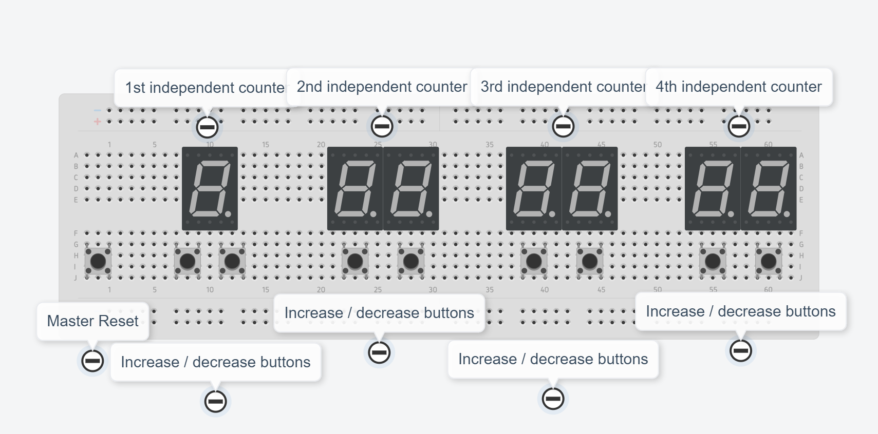
Here's a diagram of what im trying to do..... The display on the right works perfectly.
The one on the left is the one i need to get working with the additional buttons.

The idea being i want to add a few more to this as well so it needs to be scalable.
This is my code i'm using.... (modified from the original on Simple Circuit) which works fine for the 2 digit display on the right.
/*
 * 7-segment display with 74HC595 shift register
 * 2-Digit counter example.
 * Common anode 7-segment display is used.
 * This is a free software with NO WARRANTY.
 * https://simple-circuit.com/
 */

// counter button definition
#define button1    A0 // increase
#define button2    A1 // decrease
#define button3    A2 // reset
#define button4    A3 // increase
#define button5    A4 // decrease
#define button6    A5 // reset

// shift register pin definitions
#define clockPin  7   // clock pin
#define dataPin   6   // data pin

// common pins of the four digits definitions
#define Dig1    2
#define Dig2    3
#define Dig3    4

// variable declarations
byte current_digit;
int  count = 0;
void disp(byte number, bool dec_point = 0);

void setup()
{
  pinMode(button1, INPUT_PULLUP);
  pinMode(button2, INPUT_PULLUP);
  pinMode(button3, INPUT_PULLUP);
  pinMode(Dig1, OUTPUT);
  pinMode(Dig2, OUTPUT);
  pinMode(Dig3, OUTPUT);
  pinMode(clockPin, OUTPUT);
  pinMode(dataPin, OUTPUT);

  disp_off();  // turn off the display

  // Timer1 module overflow interrupt configuration
  TCCR1A = 0;
  TCCR1B = 1;  // enable Timer1 with prescaler = 1 ( 16 ticks each 1 µs)
  TCNT1  = 0;  // set Timer1 preload value to 0 (reset)
  TIMSK1 = 1;  // enable Timer1 overflow interrupt
}

ISR(TIMER1_OVF_vect)   // Timer1 interrupt service routine (ISR)
{
  disp_off();  // turn off the display

  switch (current_digit)
  {
    case 1:
      disp( (count / 10) % 10 );   // prepare to display digit 2 (left)
      digitalWrite(Dig2, LOW);    // turn on digit 2
      break;

    case 2:
      disp(count % 10);   // prepare to display digit 1 (right)
      digitalWrite(Dig1, LOW);  // turn on digit 1
  }

  current_digit = (current_digit % 4) + 1;
}

// main loop
void loop()
{
  if(digitalRead(button1) == 0)
  {
    count++;  // increment 'count' by 1
    if(count > 9999)
      count = 0;
    delay(200);  // wait 200 milliseconds
  }
  if(digitalRead(button2) == 0)
  {
    count--;  // decrement 'count' by 1
    if(count > 9999)
      count = 0;
    delay(200);  // wait 200 milliseconds
  }
  if(digitalRead(button3) == 0)
  count = 0;
  delay(200);  // wait 200 milliseconds
}

void disp(byte number, bool dec_point)
{
  switch (number)
  {
    case 0:  // print 0
      shiftOut(dataPin, clockPin, MSBFIRST, 0x02 | !dec_point);
      digitalWrite(clockPin, HIGH);
      digitalWrite(clockPin, LOW);
      break;

    case 1:  // print 1
      shiftOut(dataPin, clockPin, MSBFIRST, 0x9E | !dec_point);
      digitalWrite(clockPin, HIGH);
      digitalWrite(clockPin, LOW);
      break;

    case 2:  // print 2
      shiftOut(dataPin, clockPin, MSBFIRST, 0x24 | !dec_point);
      digitalWrite(clockPin, HIGH);
      digitalWrite(clockPin, LOW);
      break;

    case 3:  // print 3
      shiftOut(dataPin, clockPin, MSBFIRST, 0x0C | !dec_point);
      digitalWrite(clockPin, HIGH);
      digitalWrite(clockPin, LOW);
      break;

    case 4:  // print 4
      shiftOut(dataPin, clockPin, MSBFIRST, 0x98 | !dec_point);
      digitalWrite(clockPin, HIGH);
      digitalWrite(clockPin, LOW);
      break;

    case 5:  // print 5
      shiftOut(dataPin, clockPin, MSBFIRST, 0x48 | !dec_point);
      digitalWrite(clockPin, HIGH);
      digitalWrite(clockPin, LOW);
      break;

    case 6:  // print 6
      shiftOut(dataPin, clockPin, MSBFIRST, 0x40 | !dec_point);
      digitalWrite(clockPin, HIGH);
      digitalWrite(clockPin, LOW);
      break;

    case 7:  // print 7
      shiftOut(dataPin, clockPin, MSBFIRST, 0x1E | !dec_point);
      digitalWrite(clockPin, HIGH);
      digitalWrite(clockPin, LOW);
      break;

    case 8:  // print 8
      shiftOut(dataPin, clockPin, MSBFIRST, !dec_point);
      digitalWrite(clockPin, HIGH);
      digitalWrite(clockPin, LOW);
      break;

    case 9:  // print 9
      shiftOut(dataPin, clockPin, MSBFIRST, 0x08 | !dec_point);
      digitalWrite(clockPin, HIGH);
      digitalWrite(clockPin, LOW);
  }
}

void disp_off()
{
   digitalWrite(Dig1, HIGH);
   digitalWrite(Dig2, HIGH);
   digitalWrite(Dig3, HIGH);
}

// end of code.
How do i modify the loop to control the 2 displays separately?
Once i know how to do it for one i can crack on and do it for others myself.
And finally my second easier question is how can i modify the code to increase the button presses by 5 instead of just 1.
Many thanks