Hey all! I want to thank you all for any advice you can provide ahead-of-time. I also hope I'm entering this all right, as I am new to posting in the forums.
I have a project of a workbench that I plan to place on a fairly unlevel floor. My plan is to build telescopic legs for the bench and enclose a stepper (4 total motors) into the top of each leg to control the height/level of the bench. I see lots of posts regarding controlling multiple motors simultaneously, but none that seem to answer my specific question(s).
Because I want the motors to control the height AND level of the bench, I want to be able to control each one from an individual switch to initially level the legs out, then be able to use one single switch to control all of them simultaneously. Is this something I will be able to handle in programming, and have the capability do do with the Uno kit I have on the way? Or will I be better off building my control switches in such a way that one main switch can override the other four and [essentially] mechanically operate all four other switches simultaneously?
I have ordered a generic kit from Amazon to demo my ideas and do some trial and error. If it works out well enough I will use this kit in the final project, but I want the bench to look and feel professional, so I'm fully prepared to invest in higher quality parts if necessary. The kit is no longer on Amazon and I'm currently having a hard time finding the exact link to make the details easy for you guys, but I'll do my best to provide everything below:
-Arduino UNO with a CNC shield (I don't have the name or picture of the shield)
-4x NEMA 23 steppers
-4x TB6600 controllers
The kit also has four limit switches included, but I also ordered a separate pack of 10 because I assume I will need 8 total, for the top and bottom stop on each motor.
Please be critical, as I am pretty new to the Arduino world, and attempting to learn and understand this topic as thoroughly as possible. Thanks again for any feedback!
Edit
I found a screenshot I took of the kit before I ordered:
Absolutely! I should note that I when leveling the other 3 legs, I will likely be placing a level on top the bench front/back and side/side. Once level, the main switch to control all four legs at the same time is all I would expect to use unless the bench was moved and needed re-leveled.
Sure. it doesn't look like speed is a problem, so handling 4 motors should be fine. You will be able to control them separately and in combination. Not entirely sure you have a need for limit switches.
If you have 4 motors, plus 4 limit switches, plus 5? switches for control, you might be running short of IO pins.
I am wondering about the mechanical solution for the telescoping mechanism. I would probably have chosen linear actuators for this type of application.
Thanks! As far as speed, I want to do something where maybe a tap of a switch controls only a few pulses for a short movement, then holding the switch will kick it up to full speed. As far as I can tell it looks like the accelstepper library and some others may be able to cover that.
I originally thought about linear actuators, but the idea of concealing the motors inside the table legs and reducing bulk was appealing to me. I have a pretty solid mechanical/welding background, so the design of the legs will be fun for me. I plan on using an ACME threaded rod (maybe 5/8") as a lead screw, which will also bear the weight of each leg. I've got some ideas for how I will couple the lead screw to the motor inside the legs. Some R&D will definitely be involved. I have a tendency to overbuild and overengineer every project I take on -it's a blessing and a curse haha.
besides picking one leg for a standard, I would recommend starting your project with just 1 leg. Write a sketch that controls 1 motor, moving one leg up and down until it hits the high/low limit switch on that leg and properly stops. Get that working and well understood. Then add 3 more legs, they should all behave the same. Once you know all that is working, then the final piece will be to code up the "all legs moving together" portion.
Basically, start small, build, test, understand. Add more. repeat.
Don't try to write the final sketch the first time.
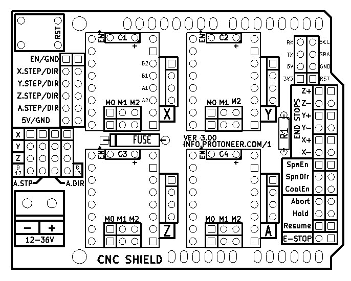
The CNC shield was intended for a different type of driver, not the ones included in the kit, so it's basically useless.
So in the simplest solution, you will need 8 pins for the motor drivers, 8 for the limit switches and 8 for the up/down switches an 2 more for the all at once switch.
That's 26 pins The Uno has 18 (not counting D0 and D1)
Folks often use that CNC shield as a breakout for an Arduino, jumpering from the bigger drivers to pins on the Protoneer-designed CNC shield.
Since the axes move from one end to the other, the shield combines the limit switches for both ends of each axis into a single pin, saving a few pins. If you need more IO, you can fit the shield onto a Mega.
The Mobatools stepper library has some good examples of individual and simultaneous movement with acceleration, using reference switches, and jog buttons. Take a look at these examples:
For this thread, the bounce-ish state machine in Mobatools Example 2 is good to understand, as well as the code in the Mobatools Reference examples.
Control-wise, one might consider an encoder, cycling modes for all-four up& down, homing, individual, left-right tilt, back-front tilt, and some canned setups, etc...
Awesome, thanks for all the info! I'll be doing some digging through all this...
Forgive the ignorance, but what do you mean by the shield being used as a break-out for the larger drivers? I looked into your links on the shield and see it's clearly designed for the smaller drivers to plug right in. Am I better off buying a whole different shield (maybe with a Mega), or is there an easy fix for adapting it to the larger drivers?
There's headers (see diagram below at the "*.STEP/DIR" labels) that expose the STEP, DIR, Enable, and end stop signals on the board, so folks hook to them. Consider if someone setup their machine with smaller steppers and drivers using the shiled, and then needed to upgrade to larger incompatible drivers for their Z axes or whatever, then they could bypass/remove the unused small driver and tap the larger driver into the STEP DIR signals on the board header without completely redoing the wiring.