To control the ball valve I need a DPDT relay, no big deal I have that covered.
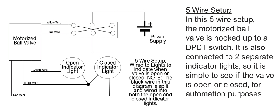
I do need to figure out how to read the wires that are meant to turn on an LED depending on what position the valve is in. so from the schematic that came with the ball valve each wire brings GND to the LED. I havent been able to find a good way of reading each pin i connect the wires to so that i can print a line that says "Valve Open" or "Valve Closed" or send myself a msg with the same info.
I have been reading and trying stuff out so I dont have any working code at the moment. I have just ordered a DPDT relay to use instead of my SPST relays i purchase prior. To test each valve position i manually power each control wire to move the valve. Thanks in advance!
I guess that you have to monitor the lights for when the desired position is reached. Or do you want analog behaviour of the valve, guided by other sensors?
The problem with a more specific answer is in the detail not supplied.
i.e. the indicators could be an LED on their own, or an LED with built in resistor etc.
The black wire is possibly an open collector arrangement given your quote .......
Sounds correct. The green and red wires are probably a transistor so to feed it into an Arduino DIO pin you would need a pullup. I would also put a 10k resistor in series right before the DIO pin so if it's not a transistor output the Arduino will be protected.
Instead of a DPDT relay you could use an H bridge driver configuration. like these.
Can you please post a link to data/specs of the ballvalve assembly?
It looks like your assembly is simply a reversible motor with inbuilt limit switches to stop the motor at each extremity of its travel.
The open close limit switches are probably part of the motor control limits.
Without the specs, I would say that they are just switches, with a common connection, using them as common gnd is the logical way to use them connected to the Arduino controller with pullup resistors.