My goal would be to control a number of these floodlights from one arduino.
My threads on this project have been merged so in this opening post I'll try to keep track of questions that I have and challenges that I face.
Challenge 1: custom colors Conclusion: Not feasible, it's a gamble and might not work. My focus will be on the communication.
==============================================================
I'm curious about the colors. The remote (APA1616) has only 16 predefined colors And well, I would very much like to make my own colors.
Is there a way of figuring out how to send custom colors by reverse engineering the protocol ?
Challenge 2: communication from one master controller to several floodlights Conclusion: None yet
==============================================================
I would like to control each RGB floodlight from one controller. That would mean some additional addressable hardware. I'm thinking of ESP's.
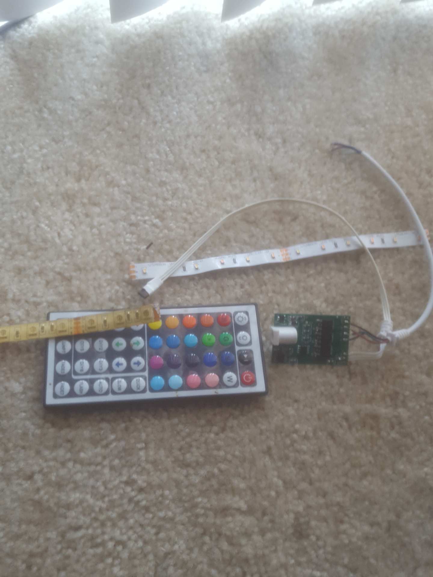
It is very interesting that I see this post because just the other day I was taking apart an RGB led strip that is very similar to yours with the same remote. Mine came with an Led driver board with an IR receiver, 3 MOSFETS(one for each red, green, blue) and an ATMEL218. For my purpose was to get rid of the RGB LEDs it came with and solder on movie/commercial grade LED that I use in film, so I cut off the connector and solders the wires to my new LEDs which are bi-color, now I can change color temperature and brightness wirelessly for less than 15$ it cost for the whole original RGB strip with controller.
I will have pictures below.
As far as your concern, did you want to control all lights with one controller? If each remote used the same IR signals and the receivers were all programmed to receive the same IR (which i think would be possible because those lights are usually pretty cheap) couldn't u just create a Reciever bus and chain them all together?? In my pic below u will see by the IR receiver it has a pin that says (R), couldn't you just connect those together and just use one remote and control all of them??
I honestly don't know myself, I will have to try for myself.
mikb55:
Is the onboard microcontroller capable of understanding colors beyond the 16 color range?
That's what I'm trying to find out
westfw:
I bought a similar unit. I haven’t done much with it other than to determine that the internal electronics are not very hackable - all encapsulated...
The electronics, yeah, I'll leave that as is. But I'm hoping to hack the IR protocol.
@tjones9163: Ah yes, I have one those for led strips too. Cool hack to use it the way you do !
And yes, controlling all lights at the same time shouldn't be a problem I think. I'm pretty sure they all respond to the same signals from the controller (F7 seems to be the address nibble?). But I would like to do the opposite, address each of the lights separately. If I hardwire each light to a different output on an arduino it's doable, wireless addressing is another challenge.
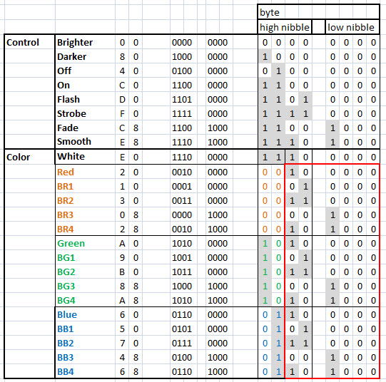
I would first like to explore the option of getting custom colors instead of the 16 available on the remote. I broke down the HEX codes into bytes and nibbles
The cells marked red, seems like that's where the magic happens.
Any thoughts on this are welcome.
The next step would be getting one of those floodlights and actually sending all possible codes in the "color-control-range"
I would however take a more thought through approach instead of firing a shotgun at it
The electronics, yeah, I'll leave that as is. But I'm hoping to hack the IR protocol.
@tjones9163: Ah yes, I have one those for led strips too. Cool hack to use it the way you do !
And yes, controlling all lights at the same time shouldn't be a problem I think. I'm pretty sure they all respond to the same signals from the controller (F7 seems to be the address nibble?). But I would like to do the opposite, address each of the lights separately. If I hardwire each light to a different output on an arduino it's doable, wireless addressing is another challenge.
I would first like to explore the option of getting custom colors instead of the 16 available on the remote.
The decimal colums in my opening post are not the way to go, I broke down the HEX codes into bytes and nibbles
The cells marked red, seems like that's where the magic happens.
Any thoughts on this are welcome.
The next step would be getting one of those floodlights and actually sending all possible codes in the "color-control-range"
I would however take a more thought through approach instead of firing a shotgun at it
Ok, i see. Good luck with that. I get some of the basics of IR , where it sends infared light pulses, like the charts you showed. would that be consided "8 bit color"?
Looks like 5 bits are used to represent the 4x6 keyboard and the remaining 3 bits of the code are all zeroes. The left two bits represent the column: left column(Red) is 00, the second (Green) is 10, the third (Blue) is 01 and the rightmost is 11. The next three bits represent the row:
0 = 000 (On)
4 = 100 (White)
2 = 010 (Flash)
6 = 110 (Strobe)
1 = 001 (Fade)
5 = 101 (Smooth)
The values represent button positions, not colors or actions. From this it is fairly clear that it is the processor in the receiver that translates button position to color (or action). You will probably need to replace the receiver in order to make it do anything different.
It is possible that some of the key codes that are NOT implemented by the remote will do something interesting. You could use an Arduino with an IR receiver and IR transmitter to see what the IR codes are and how to send the unused codes.
EDIT: Looks like the bit order is just reversed. If we reverse the two fields we get:
Columns:
0 = 00 left column (Red)
1 = 01 second column (Green)
2 = 10 third column (Blue)
3 = 11 rightmost column
DC 12V 24A 288W 44key IR Remote Controller Control RGB 3528 5050 SMD LED Strip
The 44-key remote (11 rows of 4 columns) has buttons to fade up and fade down the individual R, G, and B channels. If you are lucky the receiver you have will recognize the 44-key remote. If not, you may be able to insert the 44-key receiver in place of the 24-key receiver.
For about $5 you can get the same remote and a lower-power(2A per channel instead of 8A per channel) controller:
44 Key IR Remote Controller RGB Control Box DC 12V For LED 3528/5050 Strip Light
Both need a power supply: 12V 24A (288W) or 12V 6A (72W)
Thanks for your input John. I think however that modifications like that would take extra time, hardware and tinkering.
For this project I'll accept the limited numbers of colors and focus on controlling multiple floodlights from one controller. That would be a more valuable addition/modification than having more colors.
I do have a 44 button remote and when I get the floodlights I'll be sure to see if it does something.
OK, so custom colors is not really an option
Too much tinkering, extra hardware and unknowns.
Challenge 2: communication from one master controller to several floodlights
I would like to focus on the communication from one controller to all floodlights.
Could the following setup work ?
These lights are controlled by an IR remote. If I buy them all at once I'm pretty sure that all lights respond to the same signals. That's not what I want, I would like to set the color of each light separately. Also I would like to control them wirelessly.
I thought ESP chips might be able to do this trick with minimal additional hardware. The ESP's would be build into each light, programmed with their own unique ID. The ESP's receive a command over wifi and send the corresponding "IR code" directly to the circuitboard in the light.
One controller is programmed to be an wifi access point to which the ESP's in the lights can connect.
The controller sends messages over wifi, something like setLight(1,RED)
Each light has an ESP chip with a unique address
If the light is addressed the corresponding command "IR signal" is sent over the TXD directly to the lights circuitboard
The control codes for the lights will be programmed into the ESP that is build into the light, this way the system is expandable with lights that might use different control commands.
tjones9163:
how do you know what pins to put the transistor to IC if it is not marked what type of IC it is, and if you have Specs can you post them?
thanks
I was actually thinking that it might be possible to disconnect the original IC the does the PWM on RGB channels. Instead the outputs of the ESP would be connected to the transistors (marked "T")
mrExplore:
I was actually thinking that it might be possible to disconnect the original IC the does the PWM on RGB channels. Instead the outputs of the ESP would be connected to the transistors (marked "T")
Would that be possible ?
That's what I would do. Desolder the chips and connect the PWM output pins to the transistors. The transistors shouldn't care much what voltage they get on the Base/Gate. I think you would typically put a (~220 Ohm) resistor between the output pin and the Base/Gate of the transistor. The Base/Emitter junction of a BJT looks like a diode going to Ground so the resistor protects the pin from excess current draw and the Gate of a MOSFET acts like a capacitor which can draw a lot of current when charging up.
I bought a cheap RGB floodlight, and had a look inside.
The one I bought has RGB driver that is totally enclosed in resin
I did however find a way to control it from an arduino by a little hacking...
WARNING: This is what I did and it works.
Trying this yourself is completely at your own risk.
The driver has 4 wires to the led:
black: +12, constant current.
red/green/blue: these are pulled to ground by PWM to mix colors.
If you set the light to white using the remote the red/green/blue wires act as ground.
So I set the color to white en connected the red, green and blue wire to act as one common ground.
From there it's basically using 3 resistors and 3 transistors/mosfets to control the RGB levels from an arduino using PWM pins