I have a code that is turning on and off two DC motors.
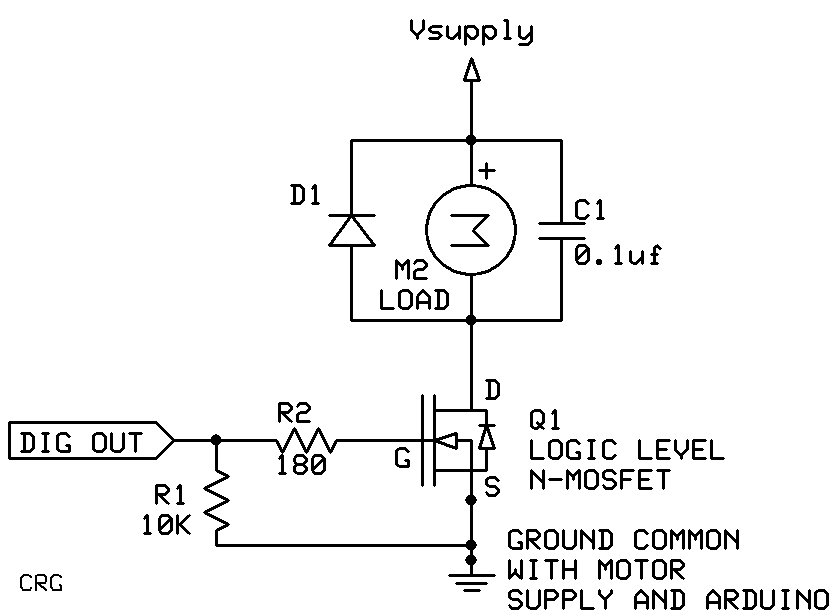
I wonder if my electronic schematics is correct?
I'm using those relays
Each motor have is own 12V PSU

edit: the way my schematics are now - I'm switching the VCC of the PSU on and off. is it better to switch the ground? or my schematics are fine? what is more typical? is there a difference at all?
edit2: here is the full code:
const int ledPin1 = 2;  // Pin for LED 1
const int ledPin2 = 3;  // Pin for LED 2

float durations1[] = {10, 5, 10, 5};  // Durations for LED 1 in seconds
float durations2[] = {5, 10, 5, 10};  // Durations for LED 2 in seconds

int numDurations1 = sizeof(durations1) / sizeof(durations1[0]);  // Number of durations for LED 1
int numDurations2 = sizeof(durations2) / sizeof(durations2[0]);  // Number of durations for LED 2

int currentState1;  // Current state index for LED 1 (starting from 1 to indicate initial ON state)
int currentState2;  // Current state index for LED 2

byte ledState1;  // LED state for LED 1 (HIGH = on, LOW = off)
byte ledState2;  // LED state for LED 2 (HIGH = on, LOW = off)

unsigned long previousMillis1 = 0;  // Previous timestamp for LED 1
unsigned long previousMillis2 = 0;  // Previous timestamp for LED 2

void setup() {
  pinMode(ledPin1, OUTPUT);
  pinMode(ledPin2, OUTPUT);
  Serial.begin(9600);

  ledState1 = HIGH;  // Set initial state of LED 1 to ON
  currentState1 = 0;  // Reset the state index of LED 1 to the first state
  digitalWrite(ledPin1, ledState1);  // Apply the initial state to LED 1

  ledState2 = HIGH;  // Set initial state of LED 2 to OFF
  currentState2 = 0;  // Reset the state index of LED 2 to the first state
  digitalWrite(ledPin2, ledState2);  // Apply the initial state to LED 2
}

void loop() {
  updateLed1();
  updateLed2();
}

void updateLed1() {
  unsigned long currentMillis = millis();

  // Check if enough time has passed for the current duration of LED 1
  if (currentMillis - previousMillis1 >= durations1[currentState1] * 1000) {
    // Toggle the LED state for LED 1
    if (ledState1 == HIGH) {
      ledState1 = LOW;
    } else {
      ledState1 = HIGH;
    }
    // Update LED 1
    digitalWrite(ledPin1, ledState1);

    // Print LED 1 state and time of state change
    if (ledState1 == HIGH) {
      Serial.print("LED 1 ON - ");
    } else {
      Serial.print("LED 1 OFF - ");
    }
    Serial.println(currentMillis);

    // Move to the next state for LED 1
    currentState1 = (currentState1 + 1) % numDurations1;

    // Reset the timer for LED 1
    previousMillis1 = currentMillis;
  }
}

void updateLed2() {
  unsigned long currentMillis = millis();

  // Check if enough time has passed for the current duration of LED 2
  if (currentMillis - previousMillis2 >= durations2[currentState2] * 1000) {
    // Toggle the LED state for LED 2
    if (ledState2 == HIGH) {
      ledState2 = LOW;
    } else {
      ledState2 = HIGH;
    }

    // Update LED 2
    digitalWrite(ledPin2, ledState2);

    // Print LED 2 state and time of state change
    if (ledState2 == HIGH) {
      Serial.print("LED 2 ON - ");
    } else {
      Serial.print("LED 2 OFF - ");
    }
    Serial.println(currentMillis);

    // Move to the next state for LED 2
    currentState2 = (currentState2 + 1) % numDurations2;

    // Reset the timer for LED 2
    previousMillis2 = currentMillis;
  }
}