Controlling vintage Aero gauge.

Hello all,

First of all I'm new here so greetings. :slight_smile:

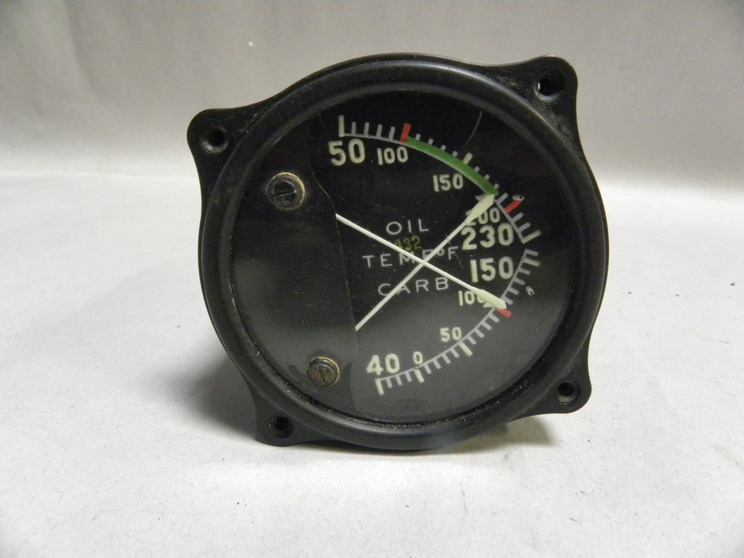
Secondly, I've been running over a vintage Aero gauge that I'd like to control with Arduino thing is I have no real data on this particular gauge with exception that it's 24 volt. In speaking with a pilot friend he's telling me that even though the gauge is 24 volt that it should respond to much lower voltages as well.

When I received the gauge I didn't even have data on the pin-out so what I did was remove the cover trace the wiring and then put .5 volts on each of the 3 pins that were not associated with GND. Even after mapping out the voltage I still sit here confused when figuring out where to start on this one. I'm attaching a picture of the mapping that I made. Also, while I hate to assume things it would appear based on how one side maps out that I may have a bad solder OR it's just by design. I'll try my best to not confuse things with this picture.

So the pin-out is A-D and from visual inspection it would appear that D is ground.

Putting power to A gives me a readout on each side as expected based on the wiring layout.

Putting power to B gives me power on both sides as does C. Basically B and C map out exactly the same even when power it applied independently to each.

The return wire marked with 'no voltage' has no voltage on it at any time when power is applied to A-C. It's hard to tell due to age if this is by nature of if I have a faulty solder. The return wire is unsheathed at the connection point and is extremely close to a solder that would put B/C power to that wire but like I said... by design or due to faulty solder.

Guess I should also mention that if I put power to D I get voltage on D/C/B but not A. Since it's a dual gauge with two needles I'd thing that two of these inputs would correspond with each needle independently so there's that.

If anyone has any ideas on where to start or better yet where you would start please feel free to chime in. I'd really like to figure out if arduino can control this gauge prior to sending it off for a $600 restoration which is apparently the going rate for Aero gauge work? :o :sunglasses:

Cheers everyone,
Brandon

Practice and practice learning how to draw a schematic that you can SHOW someone. Then you might even discover yourself how to use the device.

Paul

Hi;

So the pin-out is A-D and from visual inspection it would appear that D is ground.

Putting power to A gives me a readout on each side as expected based on the wiring layout.

Putting power to B gives me power on both sides as does C. Basically B and C map out exactly the same even when power it applied independently to each.

Readout where?
Both sides of what?
What does the "Aero Gauge" do?
What is on its face?

Thanks.. Tom.. :slight_smile:

Hi Tom,:slight_smile:

  • Readout on my multimeter from the back of the gauge

  • The wiring for pin A goes to each side of the gauge so as expected when I have power on pin A I get voltage readouts where that wiring terminates

  • The Aero gauge is just an older aircraft gauge that measures temperature (oil and carb)

  • I am attaching a picture of the front portion of the gauge.

TomGeorge:
Hi;
Readout where?
Both sides of what?
What does the "Aero Gauge" do?
What is on its face?

Thanks.. Tom.. :slight_smile:

Hi,
What happens if you put your DMM in diode mode and you connect to the different terminals and observe the meters to see if they move.

Thanks.. Tom.. :slight_smile:

Ok so I just did a diode test all over the back of this gauge as well as my other aero gauge that measures fuel-air ratios (same manufacturer) and I did get movement. I can't really map out how each needle responded based on where I checked but I can work on that it was just a quick test then I grabbed my other gauge just to see if I could get movement also. :slight_smile:

I'll report back soon.

TomGeorge:
Hi,
What happens if you put your DMM in diode mode and you connect to the different terminals and observe the meters to see if they move.

Thanks.. Tom.. :slight_smile:

Gets a bit tricky understanding meters but the page below may help getting you started.

Just be aware your meters are expanded scale, meaning they do not start at zero.

http://www.thebackshed.com/windmill/articles/ExpandedScaleVoltMeter.asp

Note that there are 3 pages all together.