sshaikh:
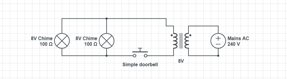
For a smart doorbell project, I'm considering using a uninterrupted 8VAC supply to provide power to a SoC module and some relays.
Should be OK.
sshaikh:
A quick google came up with this:
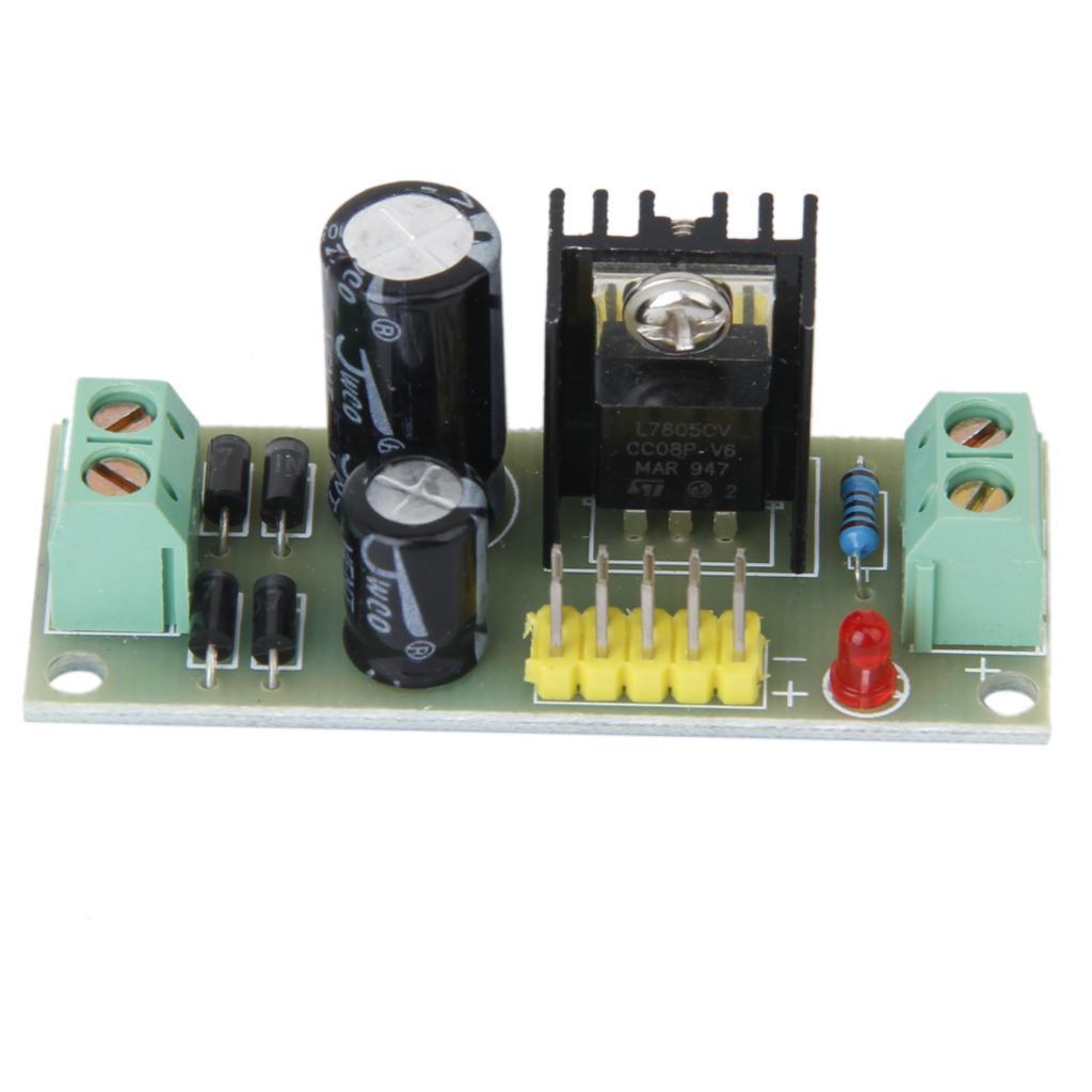
Which seems to do the trick, but uses an L7805. Is this the best way to achieve what I need? I ask because I read that it's pretty inefficient.
Ten volts in, five out. Wastes as much power as what it feeds, uses. Better not to get things any hotter than you can manage to avoid.
sshaikh:
As an alternative I also spotted this:
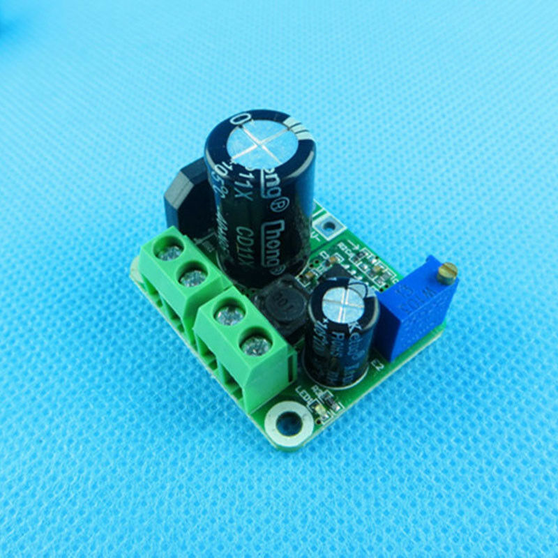
Includes bridge rectifier, and interestingly, the cheapest of those you cited. Looks good. Can't see the capacitor rating but probably adequate as claimed.
sshaikh:
But partly as a learning exercise, I'm wondering if I can do better by building my own, based on this:
How to convert 6V AC to 5V DC - Electrical Engineering Stack Exchange
Bad idea. Very bad. If you are referring to the switchmode design shown, such regulators are non-trivial to construct and operate stably - and you do not want it to misbehave in any fashion. Common discussion here, best leave it to proven designs, not to mention that it is cheaper to do so.
sshaikh:
At 8VAC, the resulting DC will be 8 x 1.414 ~ 11.31 - 1.4 ~10v. I was hoping to just use a buck after this point like this:
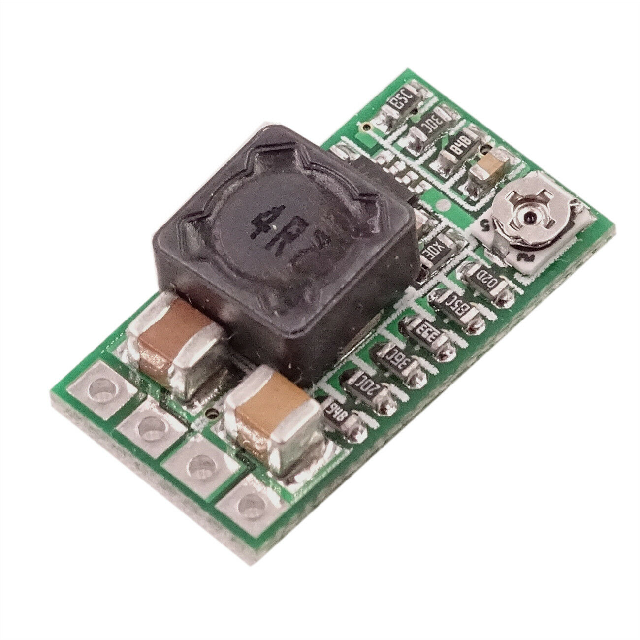
Would work, but easier to use the one with the bridge and capacitors built in. Note that the rectified voltage will peak at 10 V, but drop between cycles as the capacitor discharges. However this design should have relatively low "dropout" voltage (and better than the 7805), so apart from thermal efficiency, this is an advantage of the switchmode.
sshaikh:
But do I still need the various capacitors? If so, how can I work out which ones?
Use the complete module.
sshaikh:
Also can I use 1N4148 for the rectifier bridge?
Absolutely not.
sshaikh:
I said "SoC module" because I'm still not sure what I'll be using - I'll probably settle on a Wemos D32, but it might be a D1 Mini Pro instead. I actually had a look at the schematics and I think they all use a ME6211 which operates on a voltage range of 2-6v which sounds too narrow for a rectified 8vac
That regulator is intended to regulate your 5 V supply (like USB) down to 3.3 V. It is never intended to be supplied from 10 V.
sshaikh:
Also looking around I can expect these to draw around 800mA peak since they'll be using the WiFi a bit.
800 mA sounds excessive, even as peak. 300 mA more likely as I recall for the ESP8266.
sshaikh:
- The transformer idles at 9V
- It's a DAT03A which is rated at 2A
- When the button is pressed the voltage drops to 8.7V.
Door chime transformers are generally rated for intermittent use only, but the design with separate primary and secondary tends to be a sort of "choke transformer" limiting its output current.
sshaikh:
And for the chimes:
The label of the chime says AC 8V ~ 1A
About right - for intermittent use only.
sshaikh:
The resistance across the AC chime terminals (I tested both also while button was pressed which I assumed shouldn't matter but did it anyway) is around 4 ohm
And as others have explained, the inductance in addition, will limit the current to 1 A at 8 V.
sshaikh:
The voltage at across one of the chimes when the button is pressed is around 6.4V[/li][/list]
Given a few more ohms in the wire.
sshaikh:
I can't seem to measure the current with my multimeter (I later realised it only works with DC), but according to the above it draws around 1.6A (6.4v/4ohm), which sounds pretty high.
No, add the inductance, less than 1 A.
sshaikh:
So unless my schoolboy testing is in error, it sounds like the transformer shouldn't be able to provide enough current for the two chimes let alone the WeMOS/ relays. Am I missing anything?
Yep. 1 A each chime, two of them is 2 A, the WeMOS will not draw too much.
sshaikh:
Interestingly I can connect a 9V battery to it but I suppose something else is going on there.
What sort of 9 V battery? Did it do anything at all?
sshaikh:
I'm still a little confused about this.
Mmmm.
sshaikh:
The Ardiuno Uno seems to use this lp2985-33dbvr which takes in 16V which sounds quite handy.
It may be rated at 16 V, but without a proper heatsink, will be useless at anything above 8 V.
sshaikh:
However the ESP32 board I'm looking at has a ME6211 (https://wiki.wemos.cc/_media/products:d32:sch_d32_v1.0.0.pdf) which seems to take in 6v max, which I presume means the 8-15v is out?
You provide this with 5 V - five Volts - from a regulator, such as the second, switchmode, module you cited. It is designed for five Volts.
sshaikh:
Why would I go for a higher voltage anyway? For more options later? If it is handy to have then I can externally step down the input to 3.3v for the ESP32 (using what? A lp2985-33dbvr?).
Not sure what you mean.
sshaikh:
I also need 5v to feed the relays, though, so if I stuck to the 5v looking at the schematic or board photo (https://wiki.wemos.cc/products:d32:d32) I can't tell how I would provide that 5v to the board itself - there doesn't seem to be a 5v in pin?
It is labelled "USB".
So, you use this regulator module to develop stable 5 V from your 8 V transformer.
Note that now, all the 8 V AC devices must be connected separate to the 5 V system, controlled by relay contacts (or SSRs with optocouplers or such).