Counting counts by a rotary encoder

Hello everyone
I've been trying to count using a rotary encoder for a project, however, the rotary encoder counts one step then on the next step the program sort of stops and the serial monitor does so, nothing works, and then if I rotate it one step further everything goes back to normal, but it does the same thing on the next step. So at one step it stops the program and nothing runs, then at the other everything is back to normal and this keeps happening at alternate steps.
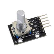
This is the encoder i am using.
encoder

below is the code.

#include <Arduino.h>
#define CLK 12
#define DIO 11

const int PinA = 2;  //PinA = CLK pin
const int PinB = 3;  //PinB = DT pin
const int PinSW = 8; //PinSW = switch pin
int lastCount = 50;
// Updated by the ISR 
volatile int count = 50;
unsigned long previoustime;
// ISR function
void isr ()  {
  static unsigned long lastInterruptTime = 0;
  unsigned long interruptTime = millis();
  // If interrupts come faster than 5ms, assume it's a bounce and ignore
 if (interruptTime - lastInterruptTime > 5) {
    if (digitalRead(PinB) == LOW)
    {count-- ;} 
    else { count++ ;}   
    //Restrict count from going above 56 and below 50
    if (count == 57){count = 50;}
    else if (count == 49){count = 56;}
   }
  lastInterruptTime = interruptTime;
}
void setup() {
  Serial.begin(9600);
  pinMode(PinA, INPUT);
  pinMode(PinB, INPUT);
  pinMode(PinSW, INPUT_PULLUP);
  attachInterrupt(digitalPinToInterrupt(PinA), isr, LOW); 
  Serial.println("Ready to go!");
}
void loop() {Serial.println(count);}

Hope everyone is able to understand what I'm trying to ask.
Thanks for your time.

This will never evaluate.

How are things wired ?

Example:
https://www.electroschematics.com/wp-content/uploads/2015/06/rotary-encoder-arduino-wiring.png?resize=305%2C183

or (use 5v)

image

1 Like

Hi Larry,
I have used the rotary encoder module directly, without adding any additional capacitors, it has the 10k ohm resistors already only the resistor dor the switch was not placed(now connected with the pullup resistor).
each pin of the encoder is connected directly to the Arduino as defined by the code, and yes I have given 5v.

Please post a link to the encoder product page or data sheet. It may not work in the way you imagine.

1 Like

I use the Encoder library to read my rotary encoders.

2 Likes

Always show us a good schematic of your proposed circuit.
Show us a good image of your ‘actual’ wiring.


Suggest you set a flag (volatile) in the ISR, use that flag in loop( ).

When the flag is set, do your time processing stuff there, reset the flag.

1 Like

With the interrupt set to LOW, is there a chance of multiple interrupts while the pin is LOW? Usually see CHANGE there.

1 Like

Hi jermington,
Here's the data sheet.
https://www.google.com/url?sa=t&source=web&rct=j&url=https://www.handsontec.com/dataspecs/module/Rotary%2520Encoder.pdf&ved=2ahUKEwihkrzw1dj6AhWVHOwKHbm0Ae4QFnoECGUQAQ&usg=AOvVaw3gHhCyMKuvA0829x1elFn4

Or possibly FALLING would give you fewer bounce interrupts.

1 Like

If you include the capacitors shown in the schematic posted by @LarryD (post #2), you do not need to debounce in software.

2 Likes

Hi Sherman,
I have tried both FALLING and CHANGE.
Both of them resulted in the same problem.
I will share more pictures of what the problem is as @LarryD said, and hopefully it will make it more clear.

I will surely try that,
But i don't think debounce is the problem.
I am going to share more pictures in a while.

What do you get with this simple test code without interrupts? I test the code on my Uno with a rotary encoder like yours and I get the expected output (see below).

const byte aPin = 2; // 4;
const byte bPin = 3; // 5;
const byte swPin = 8; // 3;
const byte ledPin = 13;

long encoderCnt = 0;

void setup()
{
   Serial.begin(115200);
    Serial.println("Encoder example\n");
   pinMode(aPin, INPUT_PULLUP);
   pinMode(bPin, INPUT_PULLUP);
   pinMode(swPin, INPUT_PULLUP);
   pinMode(ledPin, OUTPUT);
}

void loop()
{
   if (readEncoder()) // count changed?
   {
      Serial.print("Encoder count =  ");
      Serial.println(encoderCnt);
   }   
}

boolean readEncoder()
{
   boolean newEncode = false;
   static boolean last_aState = 0;
   boolean aState = digitalRead(aPin);
   boolean bState = digitalRead(bPin);
   if (aState != last_aState)
   {
      if (aState != bState)
      {
         encoderCnt++;
         //Serial.println("clockwise");
      }
      else
      {
         encoderCnt--;
         //Serial.println("counter clockwise");
      }
      last_aState = aState;
      newEncode = true;
   }
   return newEncode;
}

Encoder count = -1
Encoder count = -2
Encoder count = -3
Encoder count = -4
Encoder count = -5
Encoder count = -4
Encoder count = -3
Encoder count = -2
Encoder count = -1
Encoder count = 0
Encoder count = 1
Encoder count = 2
Encoder count = 3
Encoder count = 4
Encoder count = 5
Encoder count = 6
Encoder count = 7
Encoder count = 8

1 Like

Here is the output, it's not performing properly, I'm beginning to think that there is some manufacturing fault with the encoder.


Encoder example

Encoder count =  1
Encoder count =  2
Encoder count =  3
Encoder count =  4
Encoder count =  5
Encoder count =  6
Encoder count =  7
Encoder count =  6
Encoder count =  7
Encoder count =  8
Encoder count =  7
Encoder count =  8
Encoder count =  9
Encoder count =  10
Encoder count =  11
Encoder count =  10
Encoder count =  11
Encoder count =  12
Encoder count =  13
Encoder count =  12
Encoder count =  13
Encoder count =  12
Encoder count =  13
Encoder count =  14
Encoder count =  15
Encoder count =  16

Do you have caps, like on the schematic in post #2, from the A and B inputs to ground?

1 Like

No😅
Not yet
I don't have 100nf caps currently.
What other values would you suggest?

Do you have anything between 0.1 uF and 1uF?

Without the caps for hardware debounce, you will need to do software debounce. The Encoder library ( that I linked above) will take care of debounce.

What does "not performing properly" mean?

1 Like

Probably not, especially considering the errors in your code.

The data sheet you posted gives a code example, showing how to use the encoder without all the problems introduced by use of interrupts.

1 Like

I think you may have a fundamental misunderstanding of how the encoder works. You're trying to use one input as a step indication, and sample the other input to work out the direction. This has a serious problem. If the encoder shaft is rotating back and forth around the point where the 'clock' input changes, but not going far enough to change the other input, your counter will act as if the unit was continuously moving in one direction. You will also miss a count 50% of the time whenever the direction of movement changes.

A better way to look at the output of the encoder is to consider it as a two bit Grey Code counter. That counts in the following sequence:

     0  0
     0  1
     1  1
     1  0
     0  0

Notice that whether you count up or down, only one bit changes each time. what your code needs to do is grab both the input values as soon as either input changes. compare the current value with the previous value, and increment or decrement the count as appropriate.

I don't know how comfortable you are with bit shifting, but what I would do is something like this:

const int greyLookup[]={0,1,99,-1,-1,0,99,+1,99,-1,0,+1,+1,99,-1,0};
static int previous;
int current;

current = (digitalRead(PinA)<1)+digitalRead(PinB);
count += greyLookup[ (previous<<2) + current ];
previous = current;

What that code is doing is using the two bits from thee previous count, shifting them over and adding the two bits of the previous count. The result of that is used as an index into a table. The table values are the amount to add or subtract from the count. The values set to 99 are combinations of current and previous that can only happen if a step gets missed.

1 Like

yes it's the bounces, I have tried to fixed them using software after reading @kellygray post and will be sharing results.