Apologies for the lengthly post. My specific questions are towards the end, but I thought it would be sensible to give an overview of what I’m trying to build in case I’m asking the wrong things. I should also point out that I’m more into software engineering, and very much a novice where electronics are concerned. So the information I’ve acquired has been scavenged from the internet, and quite probably misapplied. I'm using an Arduino Mega 2560.
Anyway, the background is that I built a Midi delay unit, and thought it would be fun if I could modulate the effect with inputs from my analogue gear. Then I thought, what the hell, wouldn’t it be cool if I could patch together different midi control messages (e.g aftertouch controlling pitch bends etc), in a similar hands on way that I can patch an analogue synth with mini jack leads.
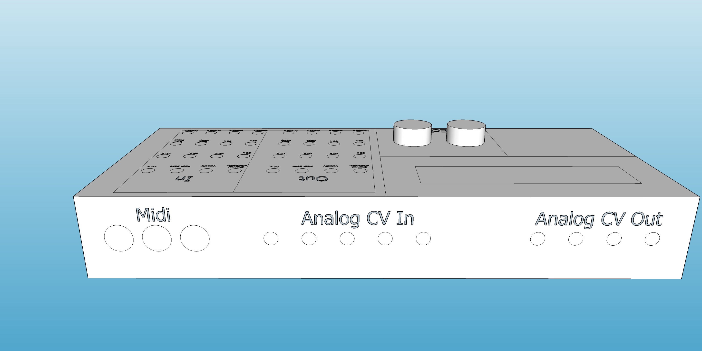
I’ve attached a couple of mock-ups to give you the general idea of the interface, but the main elements are:
Main batch bay consisting of a series of outputs for some common midi control messages (aftertouch, pitch bend etc), and inputs for both other midi control types and some parameters of the echo effect (so that echo delay could be controlled by aftertouch, for example). These cables won’t carry a signal, I’ll just periodically set each output high, poll each of the inputs and update the mapping table. Midi messages of a type that has been patched (e.g aftertouch to pitch bend) will be re-transmitted via the midi out as the new message (e.g pitch bend). If it has been patched to one of the echo or arpeggiator inputs, the value of the message will just be used to update the appropriate internal variable.
Some analog inputs. These will be on the rear of the unit. Theywill capture analog values, scale them between 0 and 127 and make them available as outputs on the main patch bay (see above).
Some analog outputs. Again, these will be on the rear of the unit, with the intention being to send analog voltages into modular equipment. They will be patchable from the main panel (e.g output for midi aftertouch could be patched to ‘analog out’ input on the main patch board, and the 0-127 midi parameter converted to a voltage between 0-5v on the rear output.
Hopefully that all makes some degree of sense. My questions are
Questions/Issues:
Protection of the output jacks. I read somewhere that a 1k resisters and a 1N4148 diode offers a sensible level of protection. Does that seem reasonable?
Protection of the input jacks. How can I give the input a sensible level of protection from someone patching something that exceeds the 5v safe voltage (or any other issue that I might not have thought of). There are quite a few inputs, so cost is a factor here.
Analog inputs. These need to be read regularly. Is it unreasonable to poll them periodically in the main loop, or is this a poor design choice? If the latter, is there a better way?
Analog output. I think I have to smooth the PWM output of the Arduino Mega. A DAC would probably be ideal, but again cost is a factor. So unless there’s one that provides multiple outputs at a reasonable cost, I might have to compromise with a capacitor+resistor based low pass filter. Apparently 12hz is a sensible cutoff frequency to smooth the PWM whilst giving a reasonable response. Using a Low Pass Filter Calculator, I’ve worked out that a 100nf capactor and 132k resistor should achieve this. It seems to do a decent job, but the output still fluctuates by about 0.6v. How can I filter it further? I’ve read I should use a second order filter, but I can’t find any information on how to design one.
I’d be extremely grateful for any help and guidance you can provide. It’s just a hobby project, but I’d like to do things properly in case it does turn out to be useful and I can share the design.
Using a 1k resistor and a 1N4148 diode for output protection is a reasonable approach. The resistor limits the current, and the diode helps prevent damage from voltage spikes.
A 5.1v Zener diode in combination with a current limiting resistor (or 2) sounds like a plan. I've never actually did it that way, but it should work. A fly-back (or inline) diode, to protect against reverse (or negative) voltage. Normally speaking one would avoid an actual physical connection between audio / midi devices electronically, hence the Opto-couplers on midi-input connectors. This circuit shows how to fully do that using a standard Opto-coupler, but that is starting to look quite complex already.
I have been looking at DAC8830 icw APA277 (to have a different voltage range) Op-amp for a different project. That should be within your price range and these DAC's are SPI, That means you can just connect a whole bunch of them to the SPI pins and switch them using their CS pins.
It is not unreasonable to do so, it just depends what else you have going on. An interrupt timer could be an option, but in the end, may create more issues than it solves, if there are any issues to be solved that is. If you just read the analog inputs before you start processing what you want to do with them, that should really be all you need to do. If on the other hand your processing thread is taking a while before it reaches that point, you can opt to have a timer execute the reading and writing of those ports, or even better get it done by a separate MCU. The Mega is not super fast, so it does all depend on what tasks it needs to perform.
Sorry, I did a rubbish job of explaining this. I built a MIDI interface, per the existing spec, with the opto isolator, resistors and flyback diode. I use this interface to read message (particularly CC Changes) which then get substituted with whatever alternative CC source they've been patched to. Reading that back, it still doesn't sound much clearer...
Great, will check this out. I'd like between 4-8 outputs. Depending on cost, a couple of high res outputs combined with the lower quality filtered PWM might be an option.
Thanks. I was wondering whether I should try to use an interrupt, but as you say, it looked potentially problematic (i.e I'm not smart enough to figure out how to do it safely). I am doing a lot of work on the main loop (reading Midi, polling pins, sending Midi out) but I've tried to spread as much work across different clock cycles as possible.
Yeah yeah i think i understood this much, but for an analog signal this separation is harder to achieve.
The DAC's go at about E2,- pp, the Op-Amp is optional, the DAC can deliver 0-5v+ i would not bother with low-quality.
The issue would in some ways be latency, so as long as all of it happening within a few milliseconds it should be OK.
I think the timer1.h works on the Mega, and what you need to do will fit inside of the ISR without to much issue, read the pins and send the SPI data to the DAC's
The examples should provide you with enough information, best of course to run a functionality test without the whole program first.
Ah, ok, so you're saying that ideally I should also optically isolate the analog input and output patch cables? That makes sense. I assumed opto isolators were for digital applications only, but I see that some can deal with analog signals.
Fair point. I might give it a go with the R C filter as an experiment (sometimes bad can be good), but take on board that a DAC is the most sensible approach.
Yes unless you are powering the whole thing from a single PSU. Of course in some situations this should not be required, but if you want to make sure, that is the way togo.
Well given that Opto-Couplers are the combination of a LED and a Photo-transistor, having a dim LED should only open the transistor partly. Of course most of them are optimized for digital applications, which makes it a bit more tricky.
I've taken some time to look at opto isolators, with the hope of solving the input voltage protection at the same time. It looks as though I'll still have to protect the opto isolator from over voltage though.
As an added complication, I've also found that the conventions for euro rack output voltage is -10 to +10 volt. I thought my instrument outputs were 0 to 5 v, so I'll test this, but at a minimum I guess I need to protect against potential the negative voltage with a diode (and accept the the signal distortion if anyone plugs a device in that uses negative voltage). Ideally though, it would be great if I could scale the whole +10 to -10 volt range sensibly in software.
I found this post from someone who had a similar problem.
I guess like them, I'm essentially trying to build a CV (-10 to +10 v) to Midi device, which might be a harder technical challenge than I originally anticipated.
Well you can use Op-Amps to Bias the voltage input from -10 to +10 to 0-10 or 0-5v , but to be honest it is a bit beyond what i can explain to you for now. I am just reading up on it, for a friend who is interested in Modular Synths, but as i said, I can not explain to you how to do it exactly. I have not done it myself just yet and although it is on the list, it is not at the top. All i got from reading up on it is that it is not hugely complicated. The thing with the Opto-coupler and getting it to respond correctly actually looked more complex.
The issue remains however, that the incoming signal should be isolated first before modification (biasing is a form of modification i guess) or you will not be able to keep the power source separated.
You could also forfeit the opto-isolation and just use an Op-Amp which will be enough protection for your circuit.
An Extra Zener diode across (and somehow facing the wrong way for my instinct, it is of course facing the right way) should protect you from extreme voltages.
Thanks for all the helpful advice - it's been really helpful to talk all this through. I thought I'd done about 90% of the work, and the analog ins and outs were the icing on the cake. Now I understand there is more involved in this aspect, and that it might be better to focus on doing a bit less by focussing on MIDI and putting the analogue stuff on hold until I have a better understanding of what I'm doing. Thanks for giving me a good starting point.