I am currently set up using an ESP12E plugged into some headers on a perf board with all of the appropriate resistors, capacitor, switches and uploading code via an FTDI breakout. The chip and other circuits are being powered by an AMS1117 putting out 3.3V. I can program it and make it do things. So far so good.
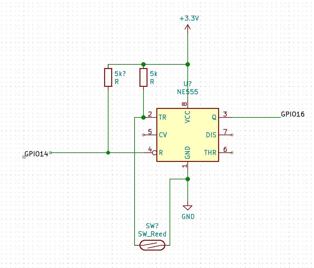
I also have a 555 timer (NE555P) set up in bistable mode as a latch circuit (1->ground; 2->5K pullup + switch to ground; 3->ESP pin(?); 4->5k pullup and ESP pin(?); 8->3.3V). Yes, I know you're not supposed to operate this chip @3.3V but it seems to work fine ex situ and it is the 555 chip I happen to have on hand (pulled out of an old garage door opener).
I've tested the circuit without the ESP12E in place by putting a LED/resistor between the output of the 555 and ground. I can turn the LED on by activating the switch attached to pin 2 of the 555 (grounding it) and turn it off by manually shorting between the appropriate header slot (pin 4 of the 555) and ground.
So now the question before I plug my chip into the headers. Do I need current limiting resistors between pins 3 and 4 of the 555 chip and their respective pins on the ESP12E? The idea is to read the high/low state of pin 3 and then reset the 555 if high by grounding 4 (usually high via 5k pullup). When it comes to electronics I am very much a newb so I don't fully understand how to determine how much current is going to flow. The data sheet for the 555 says that for Output high, no load it will max 4mA@5V .. but does my pin count as no load? The chip datasheet also speaks of supplying up to 200mA. Is sinking current on the reset pin going to effectively make a short from power supply to ground through that pin?
But uhm, what is the purpose of the 555 in the first place? What is does can probably easily be done in software....
And for a electronics answer, post a schematic. Nothing fancy but please no Fritzing breadboard mess. A simple hand drawing (pen and paper) will do just fine!
I've added a schematic to my original post. Day 1 with KiCAD but hopefully it gets the necessary information across.
As to the why of it, the circuit is to be connected to a little tilting rain gauge scavenged from a long-dead weather system. The device functions by passing a magnet past a reed switch, closing the circuit for just a moment. I've done a little testing and if you continuously read the state then no problem. Once you start adding in little delays, it becomes possible to tilt the mechanism but miss the impulse in the script. Given that the ESP is also going to be doing other things (polling a oneWire array, controlling a motor, sending data via an API call, hosting a small diagnostics page and taking in commands via web request), I want to keep the pin high until it can be read and the latch reset.
Hi All,
If you have nothing connected to the 555 pins 6 & 7, then
you do not need it. It seems like you should use a Set-Reset
Flip-Flop. The reed switch can set it to "remember" the event
until it can be processed and reset by the micro-controller.
Herb
If the 555 and the ESP are both running off 3.3V I don't see the reason for the question.
Is sinking current on the reset pin going to effectively make a short from power supply to ground through that pin?
You seem to be fairly knowledgeable about electronics. I can't help but wonder why you didn't just look at the schematic for the LM555 on the datasheet. It clearly shows the reset pin connected to the base of the Discharge pin and there is no current path to GND. The schematic is right there on the first page of the datasheet. You can't miss it.
Is there some reason you didn't look at the datasheet if it is so important ?
So, still see no need Because you should not be adding delay()'s (or other forms of delay)
And even more, in contrary to most times the topic is brought up here, this DOES seem like a perfect use of a hardware interrupt. That is basically the hardware you made with the 555 build in to the micro which will continually read the pin.
The CMOS versions of the 555, such as 7555 will work reliably at 3V, use less current and most importantly
don't crowbar the supply rail like the original 555 does....