Hi guys,
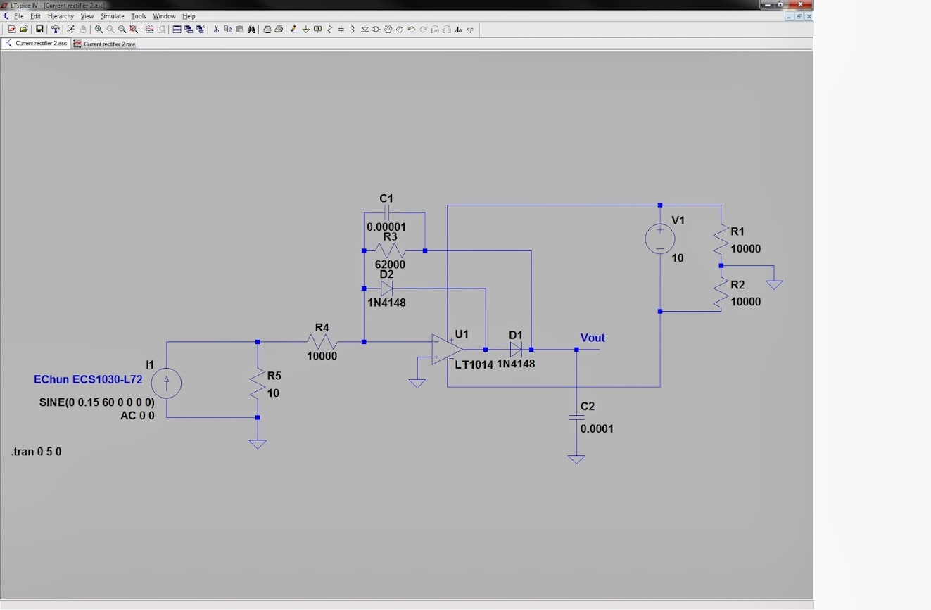
There wasn't much activity over on the sparkfun forum so I thought I'd poll the expertise, here. I have been trying to design a circuit to convert the output of the current transformer ECS1030-L72 https://www.sparkfun.com/products/11005, sold by sparkfun, to a voltage usable by an ADC or arduino. I've modified the circuit discussed in this thread: https://forum.sparkfun.com/viewtopic.php?f=14&t=28775&start=15 to sort of work with the ECS1030-L72. Below is my LTspice simulation and diagram. As you can see, the output is still a little fuzzy. I should add that the op amp is being powered by ±5v and the current source is in place of the current transformer and output and AC signal.
How would I go about filtering that residual ac noise out?
How about other options to get this to interface with a micro controller easily?
How would I have to adapt this circuit for higher current sensors by EChun (70A, 100A)? I'm assuming no modification is necessary, it would just decrease the measurement resolution.
Any other suggestions to make this work properly?
I've seen the openenergymonitor example and others, but I'd like to have the rectification happen before the input.
I'm not sure about how it would work in real life, but in the simulator increasing or decreasing the C1 value has the effect of:
- increasing the ac waveform amplitude allowed to pass
- scaling of the overall output
- changing the reaction time of the circuit
All of these things are expected except number 1. Any ideas?
(Sorry, the images were sized incorrectly. Right click and open in a new tab to see the whole thing.)


Thanks