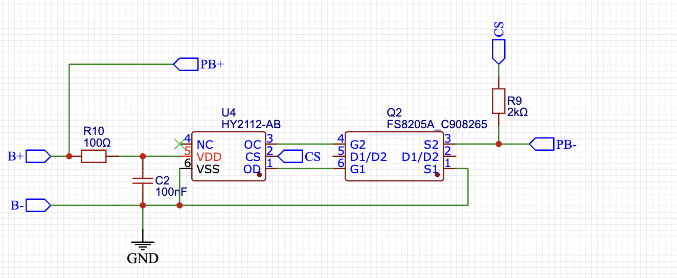
I am currently designing a protection circuit for a lifepo4 battery as a part of a bigger project. The charging is handled externally (as it is a small package) so my circuit only contains the protection circuit. I need to verify that this is the correct wiring and component choice for the application. The other thing is I want to know whether pulldown resistors are required for the FS8205. If they are, I need to know is the maximum possible resistance, as I am trying to conserve power wherever possible in this device. I have included the schematic below
Use the datasheet and application notes that usually provides examples.
You might want to consider one of the modern charger chip sets. What you are showing is a part of an old design.
This board will handle almost any battery type and power source.
No they are not.
Even though D1/D2 is connected internally, I would sill connect them externally.