Im having trouble using the max7219 to control my custom LED matrix. I currently have an 8x7 led matrix that I have soldered to a perf board and have verified all the LED's work. I removed the IC from one of the modules that comes with an 8x8 matrix and moved it to a breadboard to interface it with my matrix. I think I may have fried the IC though, as it only displays a single grid like pattern no matter what code I upload. I thought this may have come from accidentally switching the anodes and cathodes at the beginning. I ordered two new modules and took the IC out of one of them, and this time switched the anodes and cathodes to where they supposedly should be (cathodes on dig0-7, anodes on segA-F), but the same thing happened. Im down to one last IC and I don't want to fry this one as well  Ill attach photos of my setup. Any help would be appreciated! I am powering the IC with external 5v and have 5v across ~10k resistor going to Iset. What I also forgot to mention is when I take the IC out and then put it back on the module, It displays the same weird pattern. The IC's were working right when connected to the module as well before I connected it to the breadboard, so I know my code and arduino are good. I am using the max7219 data sheet for reference MAX7219/MAX7221 - Serially Interfaced, 8-Digit LED Display Drivers.
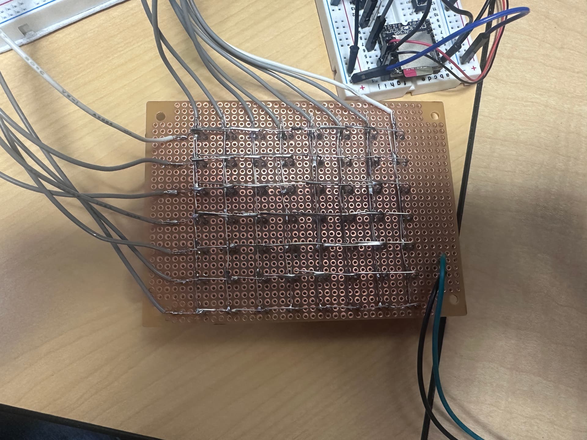
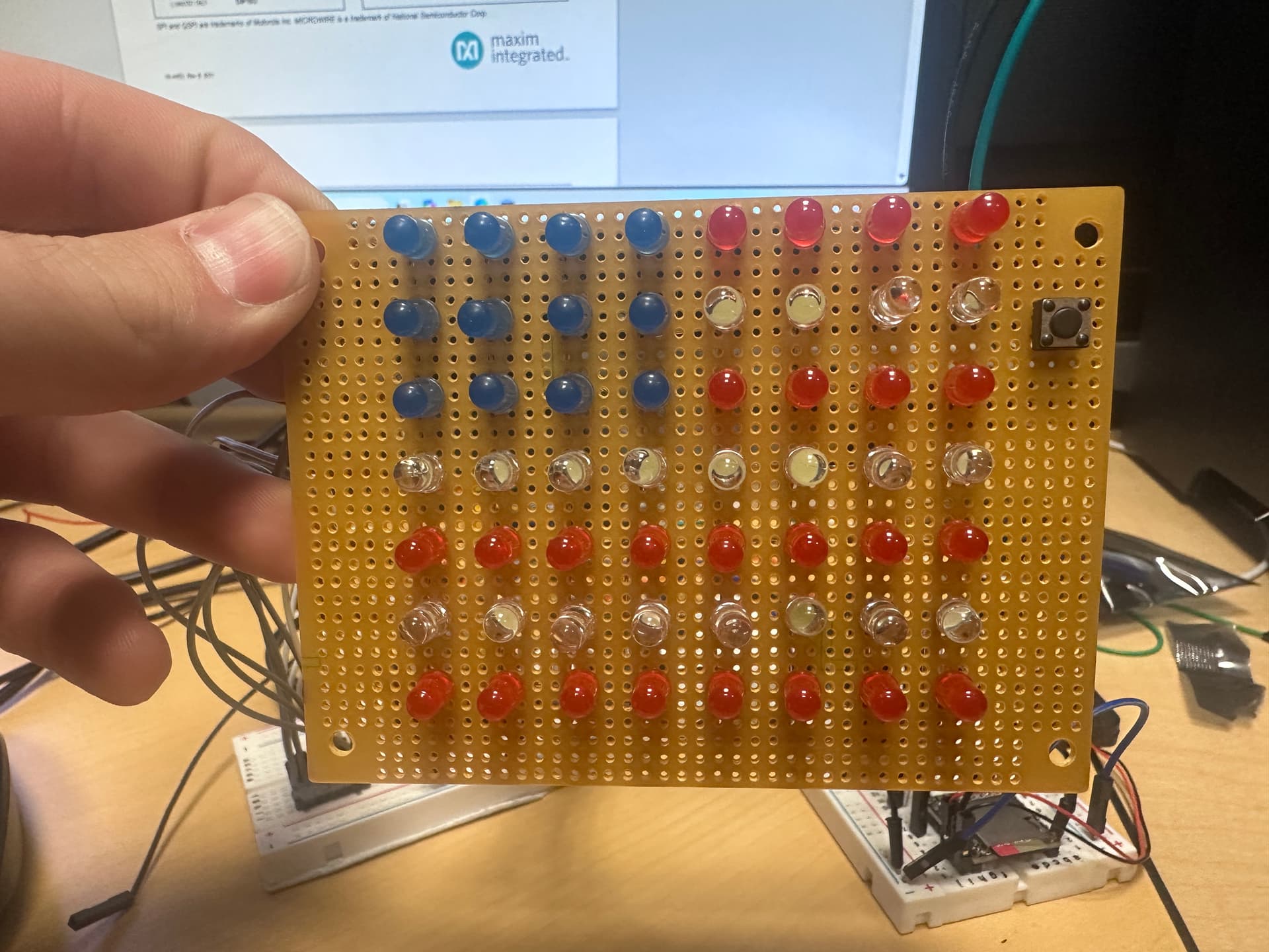

-
Always show us a good schematic of your proposed circuit.
-
Do you have I.C. decoupling on your bread board circuit ?
-
Your soldering grid looks scary

Haha thanks for the response, no I dont have any decoupling. I thought about adding it but I want to make sure theres nothing else inherently wrong before I test it and fry my last IC haha. Here is the schematic I made... Also yes the soldering was a nightmare but we pulled through haha.


How did you verify this?
Looking at your photo, my main concern is that there could be a short from columns to rows. Did you test for this? If so, how?
Im jsut realizing the schematic doesn't have it but on my breadboard I do have both grounds connected.
yes, I used my multimeter in diode mode and went through each row and column
From your photos, there is no way I can see if you have things connected right.
I will update my schematic and post it hopefully that will help
I'm not sure that would detect any shorts.
Which are connected to the rows, cathodes or anodes?

Rows are anodes, columns are cathodes. Should I do a continuity test between the rows and columns then?
From the data sheet
To minimize power-supply ripple due to the peak digit
driver currents, connect a 10μF electrolytic and a 0.1μF
ceramic capacitor between V+ and GND as close to the
device as possible. The MAX7219/MAX7221 should be
placed in close proximity to the LED display, and connections
should be kept as short as possible to minimize the effects
of wiring inductance and electro-magnetic interference.
Also, both GND pins must be connected to ground.
If your wires are too long, it is possible that the inductance is causing a large voltage spike that is destroying the IC.
For debugging purposes why don't you disconnect the matrix and just try a few LED on the breadboard.
Yes, but with your multimeter on continuity mode or resistance mode, connect the red probe to each column/cathode in turn, and for each of those, connect the black probe to each row/anode in turn. There should be no continuity/infinite resistance for each position.
Also test there is no continuity between any two row/anode pairs and no continuity between any column/cathode pairs.