I’m having a problem with my MAX7219CNG ICs (HLF brand) connected to 1088AS 8x8 LED matrices. I’m using Arduino to control them.
Problem:
All LEDs are always on and do not respond to any commands (e.g., clearDisplay, setLed, brightness).
Changing brightness, sending test mode commands, or turning off/on does not affect the LEDs.
This happens with multiple MAX7219 ICs (4 in total), and all of them behave the same.
The LED matrices themselves are fine — I tested them with another driver and they work perfectly.
Wiring has been double-checked, and I tried swapping DIN, CLK, and CS pins.
What I’ve tried (everything except the pull-up on capacitor/GND):
Using both LedControl and direct shiftOut commands.
Display test (0x0F=1) — no change.
Swapping rows/columns — then LEDs stay completely off.
Ensuring VCC = 5V and ISET pin has correct resistor (~10kΩ).
Tried multiple ICs and multiple matrices.
Tested on both Arduino Nano and Arduino Uno boards — same issue occurs.
Followed standard initialization sequences.
Setup:
Arduino Nano / Uno
MAX7219CNG (HLF)
1088AS 8x8 LED matrix
DIN → pin 13, CLK → pin 11, CS → pin 12 (I’ve tried other pins too)
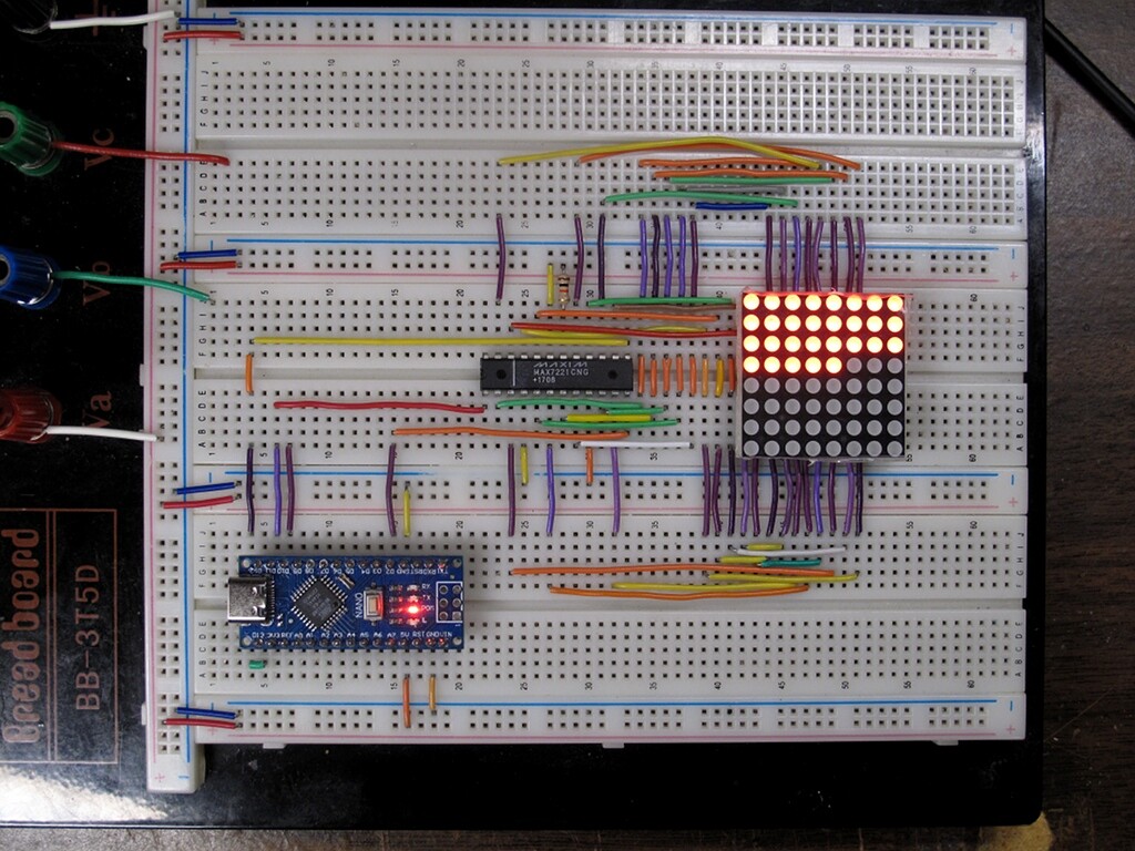
I’ve attached a photo of my wiring setup.
Could this be a MAX7219 issue, or is there something in the wiring/initialization I might be missing? Any suggestions for troubleshooting would be greatly appreciated.
Your wiring is a like a plate of multi-coloured spaghetti. It will be difficult for you and impossible for us to spot any mistakes. Also, those Dupont wires are notoriously unreliable.
I can see you have used some solid wire links laid flat to the breadboard around the display. I suggest you replace all those unreliable Dupont wires with solid core wires laid flat to the breadboard. Use several colours and use them consistently. Use red for 5V and black for ground. Then we may be able to spot any wiring errors, but be doing this you will probably find your wiring error yourself.
I cannot see the 2x caps and resistor in the photo that are shown in your schematic. These are mandatory.
I’ve checked the wiring between the matrix and the MAX7219 multiple times, and everything is correct. I also tried the circuit you suggested, but it had no effect.
( + I didn’t have enough wires to color-code them, so distinguishing by color was difficult. Instead, I’ve uploaded a photo with the matrix-to-IC wiring removed.)
I added a delay between turning on each individual LED so I could see it in action.
Works like a charm.
I included the ground connection to pin 9 of the 7219 that was missing in your partial schematic. I can't tell if it was missing in your wiring or not.
And I used a different CS_PIN.
On the balance of probabilities, you've got a bad 7219 or you've got a mistake in your wiring. If I had a nickel for every time I was sure my wiring was correct but the circuit didn't work... I've learned to assume nothing and check everything. Especially the stuff I'm sure of.